
Reinforced sealing element

a sealing element and reinforcement technology, applied in the field of heat exchange technology, can solve the problems of rotor generally deformation during operation, sealing becoming unduly worn or damaging the inner walls of the housing, and avoiding the gap between the rotor and the inner wall of the housing, so as to inhibit the damage of the sealing section

Active Publication Date: 2007-06-19
PARAGON TECH
View PDF31 Cites 18 Cited by
  • Summary
  • Abstract
  • Description
  • Claims
  • Application Information

AI Technical Summary

Benefits of technology

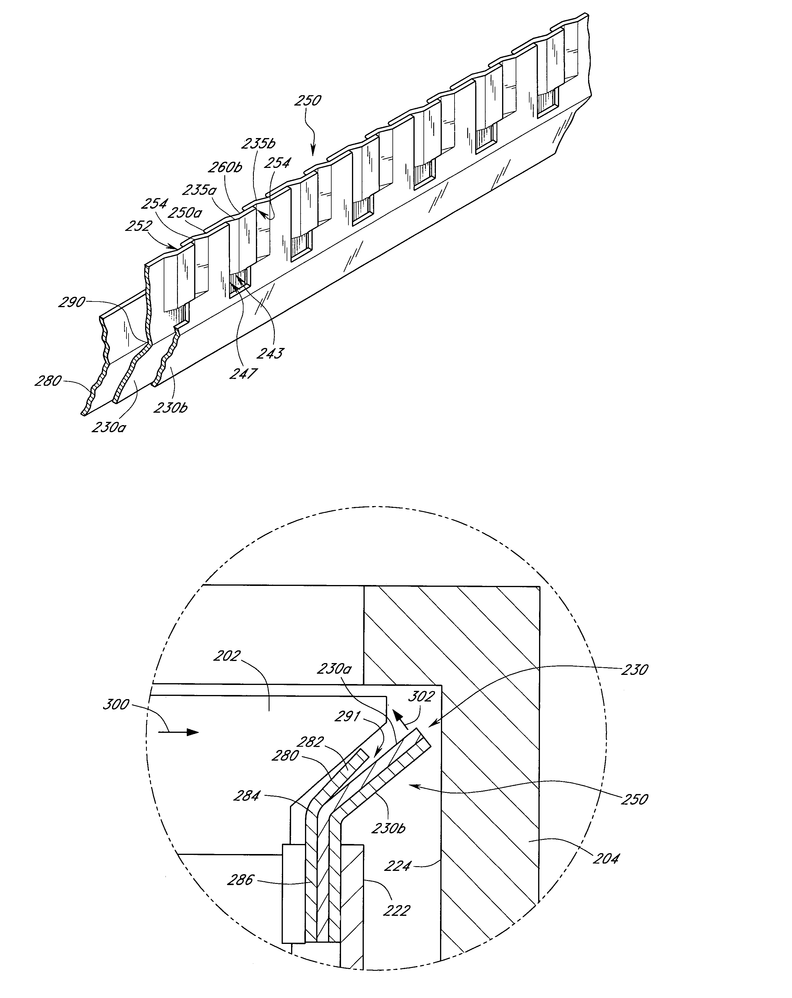
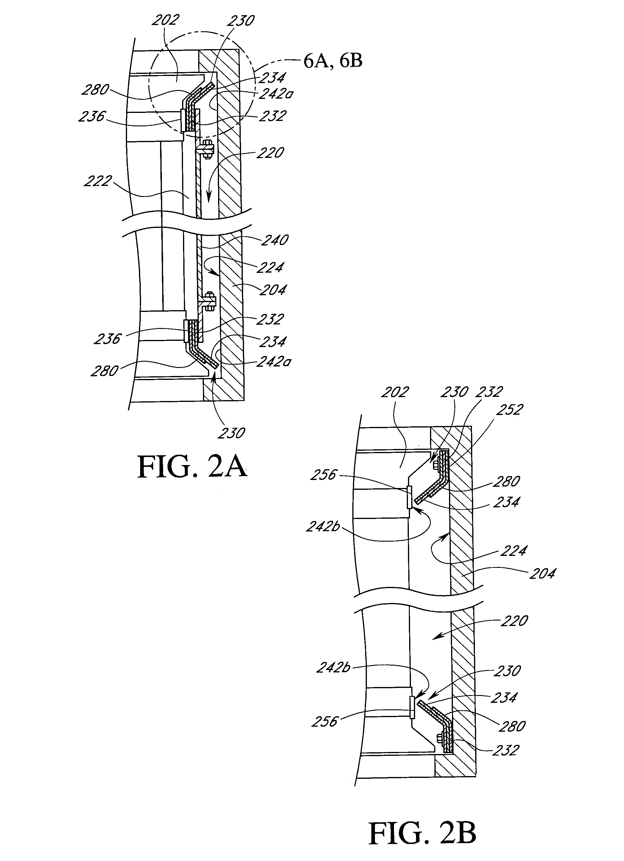
[0012]The aforementioned needs may be satisfied by a seal assembly for a regenerative air preheater having a heat exchanging body that rotates in a first direction with respect to a housing and is distally spaced from the housing so as to define a gap therebetween. In one embodiment, the seal assembly comprises a sealing section that is positioned to at least partially span the gap between the heat exchanging body and the housing, wherein the sealing section includes a deformable biasing section that engages with at least a portion of both the housing and the heat exchanging body in a manner so as to resiliently deform in a second direction relative to the first direction during rotation. In addition, the seal assembly further comprises a reinforcing member interposed between the housing and the heat exchanging body so as to cover at least a portion of the sealing section, wherein the reinforcing member is positioned with respect to the sealing section so as to reinforce the sealing section when deformed in the second direction to thereby inhibit damage to the sealing section as a result of the deformation during rotation.
[0017]The aforementioned needs may also be satisfied by a regenerative air preheater device comprising, in one embodiment, an enclosure and a rotor that rotates in a first direction with respect to the enclosure and is distally spaced from the enclosure so as to define a bypass gap therebetween. In addition, the device further comprises a seal assembly positioned to at least partially span the bypass gap, wherein the seal assembly comprises a resilient member having a deformable biasing section that resiliently deforms in a second direction relative to the first direction in response to contact with at least a portion of the enclosure during rotation, and wherein the seal assembly further comprises a reinforcing member interposed between the rotor and the resilient member that reinforces the resilient member when the resilient member is deformed in the second direction to thereby inhibit damage to the seal assembly as a result of the deformation during rotation.
[0018]The aforementioned needs may also be satisfied by a seal assembly for a regenerative preheater having a sealing surface defined between a rotor and an enclosure that rotate with respect to each other in a first direction. In one embodiment, the seal assembly comprises a sealing member positioned between the rotor and the enclosure, wherein the sealing member comprises at least two resilient sections having interlocking tabs that independently deform in a second direction relative to the first direction of rotation in response to contact with at least a portion of the sealing surface. In addition, the seal assembly comprises a reinforcing member positioned with respect to the sealing member so as to cover at least a portion of the interlocking tabs and reinforce the sealing member when the sealing member is deformed in the second direction to thereby inhibit damage to the sealing member as a result of the deformation.

Problems solved by technology

Unfortunately, a bypass gap exists between the rotor and the inner walls of the housing.
One difficulty associated with the use of these seals is that the rotor will generally deform during operation as a result of differential thermal expansion.
Unfortunately, this may result in these seals becoming unduly worn or damaging the inner walls of the housing.
However, increasing the thickness of the seal to prolong the life of the seal against damage and wear naturally results in a decrease of the flexibility of the seal.
However, such seals may fracture or break when flexibly responding to rotational stress loads produced by rotation of the heat exchanging body with respect to the outer housing of the heat exchanger.
As a result, stress fractures may allow gas leakage between conduits.
In addition, the prior art seals typically comprise gaps between the interlocking features that may also allow for some heated gases in the hot gas conduit and some cold air in the cool air conduit to bypass the heat exchanging body.
Therefore, while the prior art seals provide some improvement to efficiency loss in heat exchangers, they still result in inefficient operation as air and gases may bypass the heat exchanging body through bypass gaps between interlocking features.

Method used


Image

  • Reinforced sealing element
  • Reinforced sealing element
  • Reinforced sealing element

Examples


Embodiment Construction

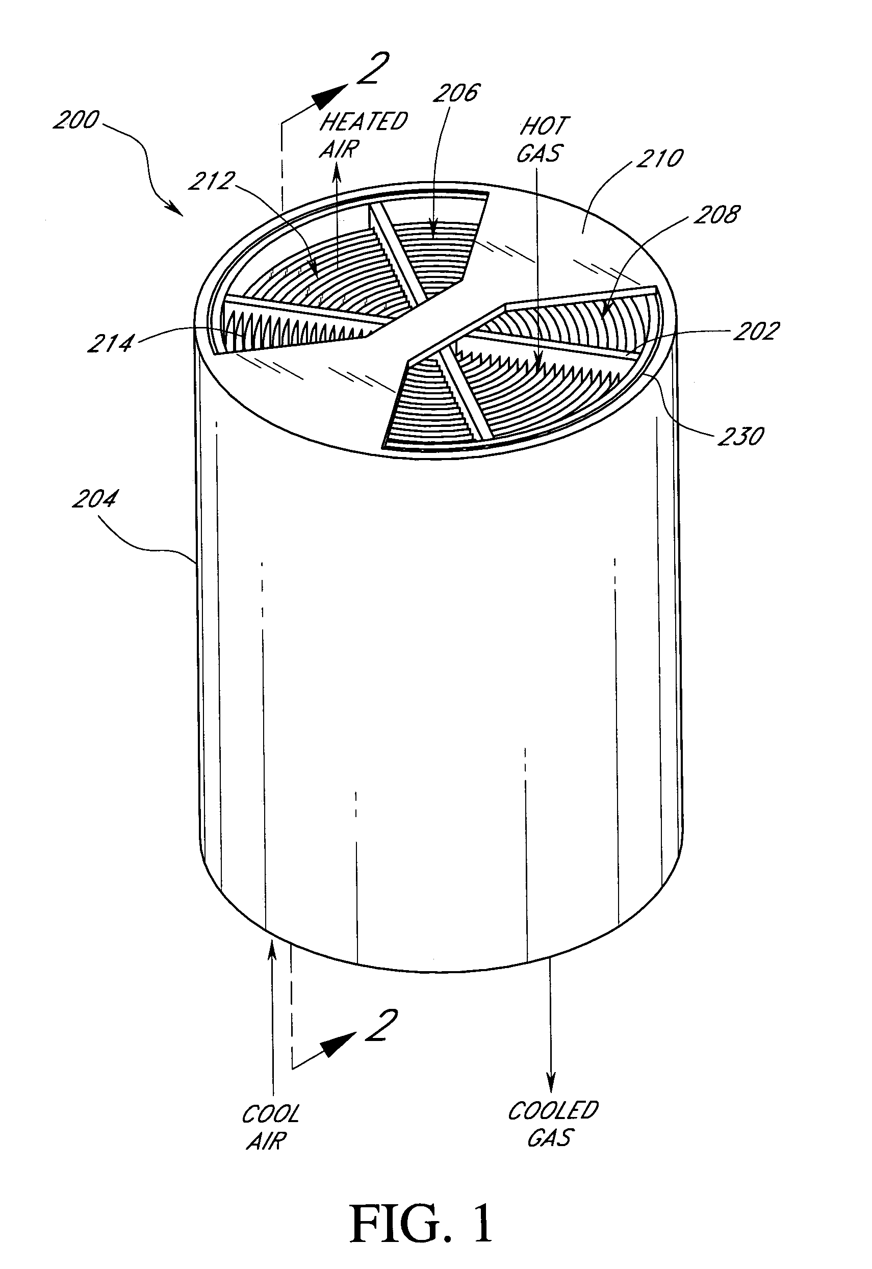
[0030]Reference will now be made to the drawings wherein like numerals refer to like parts throughout. FIG. 1 illustrates a perspective view of one embodiment of a regenerative heat exchanger 200 in which an improved perimeter seal assembly 230 having at least one reinforcing support member or section 280 (as shown in following FIGS. 2A–6) that may be utilized to reduce gas leakage. As illustrated in FIG. 1, the heat exchanger 200 may comprise a heat exchanger body 202 that is positioned within a housing 204. In this particular embodiment, the heat exchanger body 202 may comprise a cylindrical rotor that is rotatably mounted within the cylindrical housing 204 so as to be coaxial with the cylindrical housing 204. In addition, the heat exchanger housing 204 may be formed so as to define two openings 206, 208, wherein the two openings 206, 208 are respectively connected to duct work (not shown) and respectively form a portion of the intake or cold air conduit and the exhaust or hot gas...


PUM


Abstract

A seal for a regenerative air preheater. The seal is comprised of two members that each have a plurality of tabs and slots. The tabs and slots interlock so that the tabs on one member are positioned adjacent the slots on the other member. The tabs have a narrow neck section and a wider sealing section. The wider sealing sections overlay and the narrow neck sections are positioned within a recessed region of the notch on the opposite member so as to interlock the two members. The seal is mounted either to the rotor or to the inner wall of the housing so as to extend through the bypass gap between the rotor and the inner wall of the housing. As the tabs are flexible, the tabs may resiliently deform as a result of the tabs making contact with the sealing surface of the heat exchanger. The air preheater further comprises a reinforcing section that stabilizes the tabs when the tabs resiliently deform.

Description

CLAIM OF PRIORITY[0001]This U.S. patent application claims priority to U.S. Provisional Patent Application No. 60 / 415,710, entitled “Reinforced Sealing Element” filed Oct. 1, 2002, which is hereby incorporated in it entirety by reference herein.BACKGROUND OF THE INVENTION[0002]1. Field of the Invention[0003]The present invention relates to heat exchange technology and, in particular, relates to an improved seal that may be used to reduce leakage between a hot gas conduit and a cold air conduit of a regenerative heat exchanging system.[0004]2. Description of the Related Art[0005]Conventional regenerative heat exchangers are used with many types of machinery that exhaust hot gas and operate more efficiently when supplied with preheated air. These types of machinery include power plants, chemical processors, refineries, pulp and paper mills, and ship engines. Typically, two fluid stream passages extend through a heat exchanger. The first passage is an exhaust or hot gas conduit that co...

Claims


Application Information

Patent Timeline
IPC IPC(8): F23L15/02
CPCF23L15/02F28D19/041F28D19/047Y10S165/02Y02E20/34
Inventor KASER, JACKKASER, DEBORAH
Owner PARAGON TECH
Learn More