Surgical microscope drape with removable lens assembly

a surgical microscope and lens assembly technology, applied in the field of surgical microscope drape assembly, can solve the problems of inability to sterilize the surgical microscope, various disadvantages, and the area around the surgical site must remain sterile, and achieve the effect of easy removal

Inactive Publication Date: 2007-06-19
BALA ANDREW J
View PDF4 Cites 11 Cited by
  • Summary
  • Abstract
  • Description
  • Claims
  • Application Information

AI Technical Summary

Benefits of technology

[0020]The window, located on the window support, is thus located within the cavity of the objective lens barrel when the outer surface of the frame engages the inner peripheral wall of barrel. The location of the window within the cavity is advantageous because it results in a reduced working distance (depth) of the microscope head during surgical procedures and a minimization of surgical interference and of viewing obstructions from occurring on the window itself. The window of the view portal intersects a pair of viewing axes defined by the ocular ports of the microscope and an illumination axis defined by an illumination source within the microscope when the frame is mounted on the barrel.
[0021]The window of the view portal is flat and acutely inclined to minimize glare from the illumination source, with the window defining a plane acutely inclined in relation to the central axis of the frame or in relation to the illumination axis of the microscope and the upper surface of the window receiving the illumination axis from the illumination source. In another embodiment of the invention, the anti-glare properties of the inclined window are enhanced through the addition of at least one layer of anti-reflective coating to at least the upper surface of the window receiving the illumination axis from the illumination source.
[0023]A particularly preferred aspect of the present invention provides a lens assembly that is removable mountable within the cylindrical frame of the view portal. The lens assembly includes a window secured to a window support that can be easily removed from the view portal and replaced with a new window support and window. Multiple lens assemblies can be packaged together with a microscope drape to form a kit.

Problems solved by technology

However, during an operation, the area around the surgical site must remain sterile.
As it is difficult or impossible to sterilize the surgical microscope, it is common practice to cover the microscope with a sterile drape.
However, various disadvantages have been realized in trying to adapt sterile drapes to surgical microscopes.
One disadvantage arises because many hospitals utilize different configurations of microscopes to perform different types of surgical procedures.
Although such drapes have proven sufficient for use with microscopes configured for cranial operations, with the three ocular pockets accommodating the up to three ocular ports located on one side of a microscope, they prove insufficient during cranial operations requiring the use of four ocular ports.
Furthermore, the prior art drapes, having up to three ocular pockets located side-by-side of one another, prove insufficient for use during cranial procedures utilizing as few as two ocular ports, with the two ocular ports used during such procedure being located preferably 180 degrees from one another.
Such stretching usually causes tension at some portions of the drape, especially at the joint between the main cover portion and the ocular pockets, thus causing the drape material to deform, rip or rupture.
Such a rupture compromises the sterile field established by the drape, requiring a replacement of the drape itself.
Furthermore, in positioning the prior art drapes on the microscope to accommodate the opposing ocular ports, a tearing of the drape may occur around the drape's lens cover, which is typically mounted to the objective lens barrel of the microscope, again compromising the sterile field.
Although such tearing may be avoided through a rotation of the lens cover about microscope's objective lens barrel, a rotational adjustment of the lens cover about the barrel may interfere with the optical quality of the image received through the objective lens and drape lens cover.
Another 
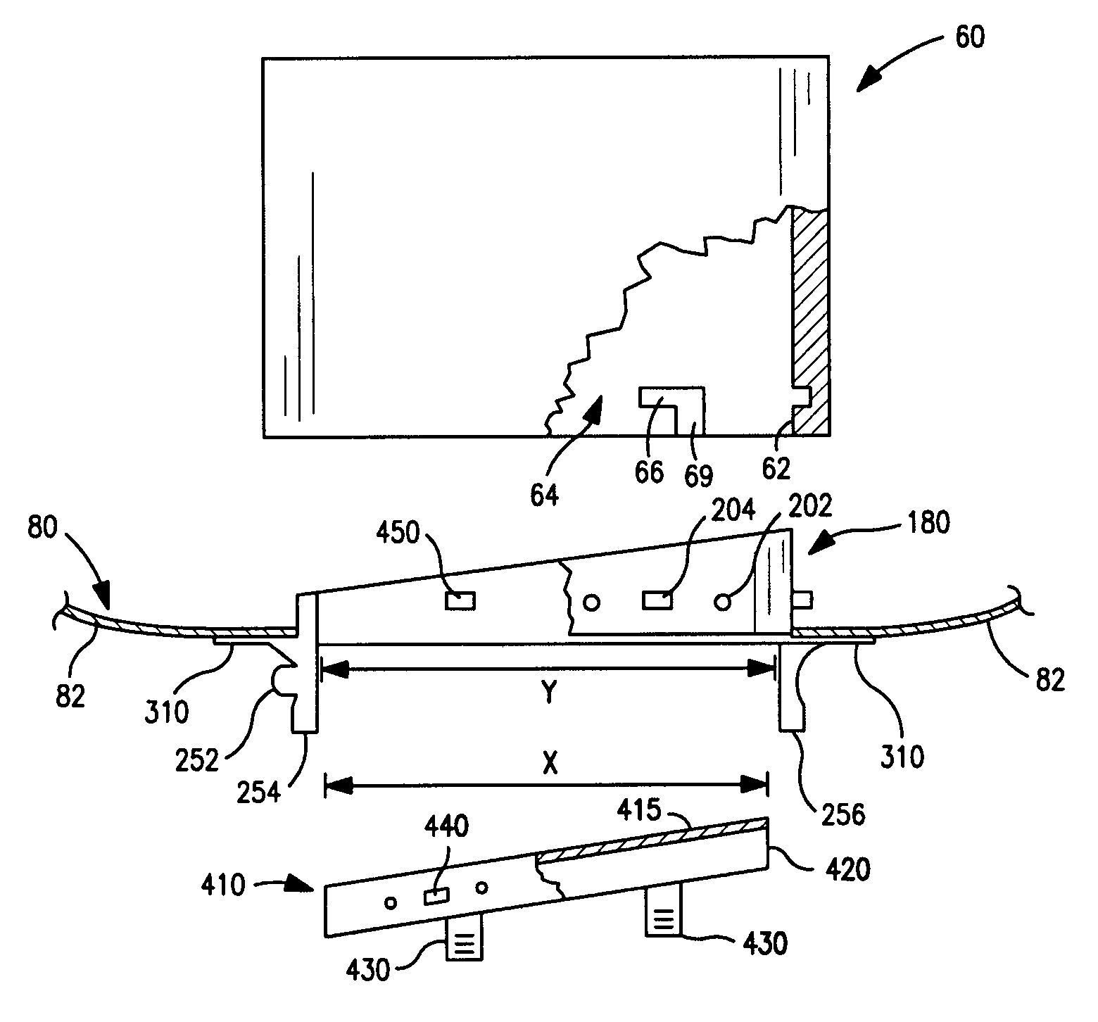
disadvantage associated with prior art drapes arises where the lens cover of such drapes is mounted to the objective barrel such that the lens or window of the cover is located below the lower end of the barrel itself.
Such drape lens covers thus result in an increased working distance (depth) of the microscope head during surgical procedures.
This increased depth of the microscope results in longer working distances for the surgeon, thus requiring the surgeon to extend his or her arms during surgical procedures performed while viewing the surgical site through the microscope.
An increased extension of the arms of the surgeon thus results in the surgeon having reduced surgical control, increased arm and hand fatigue and decreased hand and finger dexterity.
The location of the drape window below the objective lens barrel also results in the window being located towards the surgical site, thus increasing the likelihood of the occurrence of view obstructions on the window due to blood or tissue particles contacting the window itself.
Thus, a window location below the objective lens barrel increases the possibility of the surgeon contacting the window with his or her hands, with such contact again resulting in viewing obstructions occurring on the window.
Undesirable complications may also arise where the placement of the drape window below the lens barrel interferes with the surgical procedure itself.
For example, the distal end of a surgeon's hand-held instruments may contact or collide with the window during use, thus resulting again in viewing obstructions occurring on the window.
Such a collision of the instrument with the window may also interfere with the surgical procedure itself, thus slowing the procedure or adversely affecting the interaction between the instrument and the tissue contacted thereby within the surgical site.
Another disadvantage associated with prior art drapes thus arises where the lens cover results in a degraded optical quality of the viewed image due to a reflection of light from the microscope's light source off of the window of the drape lens and towards the objective lens of the microscope, resulting in glare.
However, such lenses may cause a distortion of the view of the operative field, resulting in some surgeons discarding the lens or window of the drape lens cover during a given surgical procedure, thus compromising the sterile field around the microscope.
With the drape window removed, bacteria or other contaminants present on the objective lens of the microscope itself may fall into the surgical site, thus increasing a likelihood for the occurrence of infection.
A removal of the drape window also causes the objective lens of the surgical microscope itself to become exposed to blood and other fluids so that frequent cleaning may be required, thus increasing the potential to scratch or damage the objective lens, an expensive component of the surgical microscope.
Finally, a curved drape lens or window results in an undesirable diffraction of a laser beam projected through the lens during image-guided surgeries.
Another problem that arises during certain surgical procedures such as power drilling on bone is that the lens can be obstructed or damaged by surgical debris.
While a window covering the lens protects the expensive objective lens of the microscope from physical damage, the optical properties of the disposable lens cover itself can be degraded from view obstructions resulting from blood, bone, or tissue debris.
Owing to their mass produced and disposable nature, lens covers packaged with surgical drape assemblies often have less than desirable optical qualities.
The additional refraction of light rays caused by a disposable lens cover leads to unacceptable optical aberrations in precise procedures such as image guide measurements.

Method used


Image

  • Surgical microscope drape with removable lens assembly
  • Surgical microscope drape with removable lens assembly
  • Surgical microscope drape with removable lens assembly

Examples


Embodiment Construction

[0032]The present invention generally relates to a drape assembly for use with surgical microscopes. FIG. 1 is a perspective view illustrating the basic components of an exemplary surgical microscope 10 to be covered by one embodiment of the drape assembly of FIG. 2. The microscope 10 is adjustably mounted relative to a floor, wall or ceiling mounted structure (not shown) with an articulated support arm 20 supporting a microscope head 30. The microscope head 30, mounted to the free end of the support arm 20, includes at least first and second ocular ports 40 and 50, an objective lens barrel 60, and an illumination source (not illustrated) for illuminating the operative field viewed through the microscope.

[0033]FIG. 2 illustrates one embodiment of the microscope drape assembly 70 that covers the surgical microscope 10 of FIG. 1 while FIGS. 3 and 4 illustrate more detailed views of the view portal of the assembly. In the embodiment shown in FIG. 2, the drape assembly 70 comprises an e...


PUM

PropertyMeasurementUnit
angleaaaaaaaaaa
angleaaaaaaaaaa
angleaaaaaaaaaa

Abstract

The present invention relates to a surgical microscope drape with a removable lens assembly for use with surgical microscopes. The drape assembly comprises an elongated hollow enclosure of sheet-form material having a first end defining an access opening and a second end defining a hole and at least four ocular pockets. The access opening enables the drape assembly to be pulled over the body of a surgical microscope while the four ocular pockets each cover corresponding ocular ports of the microscope. A view portal located on the enclosure at the hole is adapted to be located within a cavity of the objective lens barrel. The portal houses a removable lens assembly that includes a window. Multiple lens assemblies can be packaged together with a microscope drape to form a kit.

Description

CROSS-REFERENCE TO RELATED APPLICATIONS[0001]This application is a continuation-in-part of application Ser. No. 10 / 395,757, filed Mar. 24, 2003 now U.S. Pat. No. 6,902,278 by Andrew J. Bala, which is hereby incorporated by reference.TECHNICAL FIELD OF THE INVENTION[0002]This invention relates to a surgical microscope drape assembly, the assembly providing a removable lens window covering.BACKGROUND OF THE INVENTION[0003]Microscopes are often used in operating rooms during surgical procedures. During many of these procedures, such as spinal and cranial procedures, the surgeon must manipulate exceptionally small blood vessels, nerve bundles, muscles, nerves and other tissue. These procedures require viewing the surgical site through a surgical microscope so that the fine details in the surgical site can be clearly seen by the surgeon. However, during an operation, the area around the surgical site must remain sterile. A surgical field, as present in a typical hospital's operating room...

Claims


Application Information

Patent Timeline
Patent Type & Authority Patents(United States)
IPC IPC(8): A61B19/08G02B21/00
CPCA61B19/081G02B7/001G02B21/0012G02B27/0006A61B19/026A61B19/5223A61B50/30A61B46/10A61B90/20G02B1/11
Inventor BALA, ANDREW J.
Owner BALA ANDREW J
Why Eureka
Try Eureka