Objective lens light window flange and vacuum cavity using the flange

A technology of objective lens and light window, which is applied in the field of vacuum cavity, can solve the problems of small numerical aperture of objective lens, low resolution, long working distance of objective lens, etc., and achieve the effect of shortening working distance, high resolution and large numerical aperture

Active Publication Date: 2021-09-24
SUZHOU INST OF NANO TECH & NANO BIONICS CHINESE ACEDEMY OF SCI
View PDF3 Cites 0 Cited by
  • Summary
  • Abstract
  • Description
  • Claims
  • Application Information

AI Technical Summary

Problems solved by technology

In the process of testing the luminescence spectrum and photovoltage spectrum of materials in a vacuum or ultra-high vacuum environment, there will be energy loss caused by the reflection of the light window during the transmission of optical signals between the focusing micro-optical system and the vacuum cavity, which cannot Maximize the use of the performance of specific wavelengths. In addition, the optical signal passes through the objective lens and then through the optical window. The working distance of the objective lens is long, the numerical aperture of the objective lens is small, and the resolution is low.

Method used


Image

  • Objective lens light window flange and vacuum cavity using the flange
  • Objective lens light window flange and vacuum cavity using the flange
  • Objective lens light window flange and vacuum cavity using the flange

Examples


Embodiment Construction

[0023] Below in conjunction with accompanying drawing, the specific embodiment of the objective lens light window type flange that the present invention provides is described in detail, wherein in order to clearly describe the technical scheme of the present invention, the size of part structure is exaggerated, and it does not represent the actual size of this structure, accompanying drawing It is only used to show the connection relationship between the various structures.

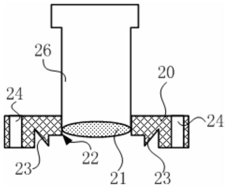
[0024] figure 2 It is a structural schematic diagram of the first embodiment of the objective lens light window type flange of the present invention. see figure 2 , The objective lens light window flange of the present invention includes a flange plate 20 and a lens 21 .

[0025] The flange 20 is connected with the external device to fix the flange on the external device. In this embodiment, the flange 20 is provided with a plurality of connecting holes 24 . Connecting member 25 (shown in Figure 4...


PUM


Abstract

The invention provides an objective lens light window type flange and a vacuum cavity using the flange, comprising a flange plate and a lens, the center of the flange plate has a through hole, and the through hole forms an optical path channel. A lens is arranged in the optical path channel to form a light window, and the lens is used as an objective lens front lens of an optical system. The advantage of the present invention is that the objective lens and the flange are combined as a whole. The light window on the conventional flange is replaced by the objective lens. After the light beam is transmitted by the objective lens, it does not need to pass through the plane lens light window, thereby reducing the energy loss of the light source caused by the reflection of the light window. At the same time, the working distance of the objective lens can be shortened. Short objective lenses have a large numerical aperture and high resolution.

Description

technical field [0001] The invention relates to the field of optical design, in particular to an objective lens light window flange and a vacuum chamber using the flange. Background technique [0002] Low-temperature photoluminescence (PL) spectroscopy can test the fundamental physical properties of semiconductor materials. The sample in the low-temperature sample chamber emits light under the irradiation of the focused laser beam whose energy of the excitation light source is greater than the forbidden band width of the material to be tested. The emitted light is collected by the lens and then received and identified by the photodetector. The photoluminescence process of semiconductors contains material structure and composition information, which is a comprehensive reflection of various complex physical processes. Therefore, photoluminescence spectroscopy can be used to obtain a variety of essential information of the studied material. [0003] The atomic force microscop...

Claims


Application Information

Patent Timeline
Patent Type & Authority Patents(China)
IPC IPC(8): G02B7/02
CPCG02B7/02
Inventor 李爱杰谢宇辰徐耿钊刘争晖钟海舰宋文涛陈科蓓张春玉徐科
Owner SUZHOU INST OF NANO TECH & NANO BIONICS CHINESE ACEDEMY OF SCI
Why Eureka
Try Eureka