
Optical module

An optical module and beam technology, applied in the field of optical communication, can solve the problems of insertion loss, chromatic aberration and poor structural compactness, and achieve the effects of reducing insertion loss and chromatic aberration, reducing size and increasing range

Pending Publication Date: 2021-11-09
HISENSE BROADBAND MULTIMEDIA TECH
View PDF0 Cites 0 Cited by
  • Summary
  • Abstract
  • Description
  • Claims
  • Application Information

AI Technical Summary

Problems solved by technology

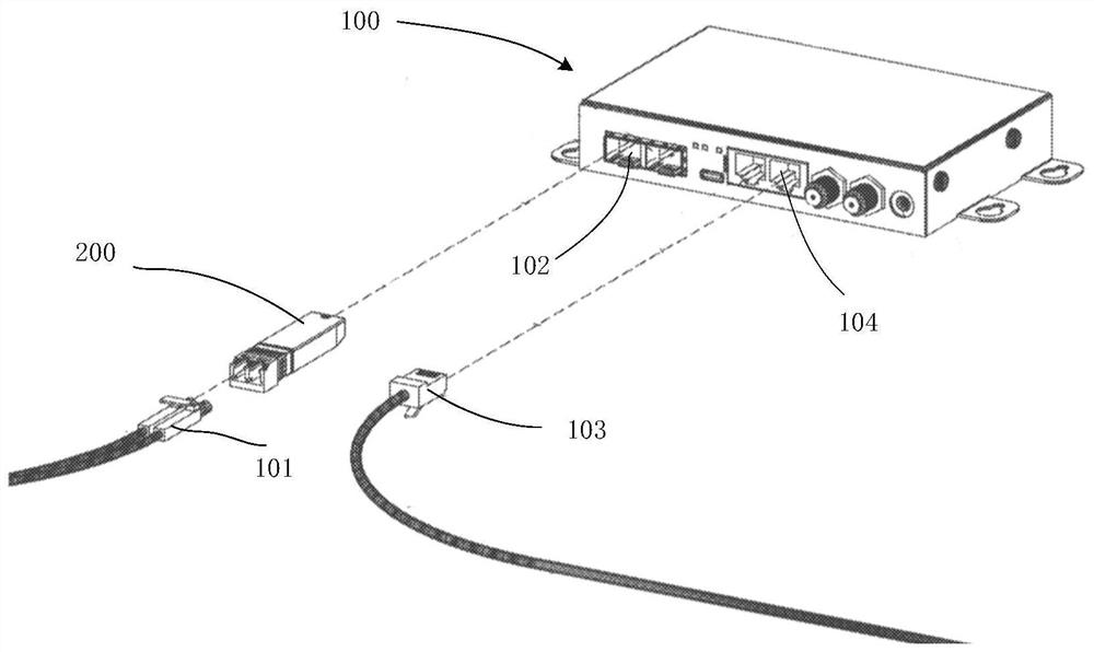
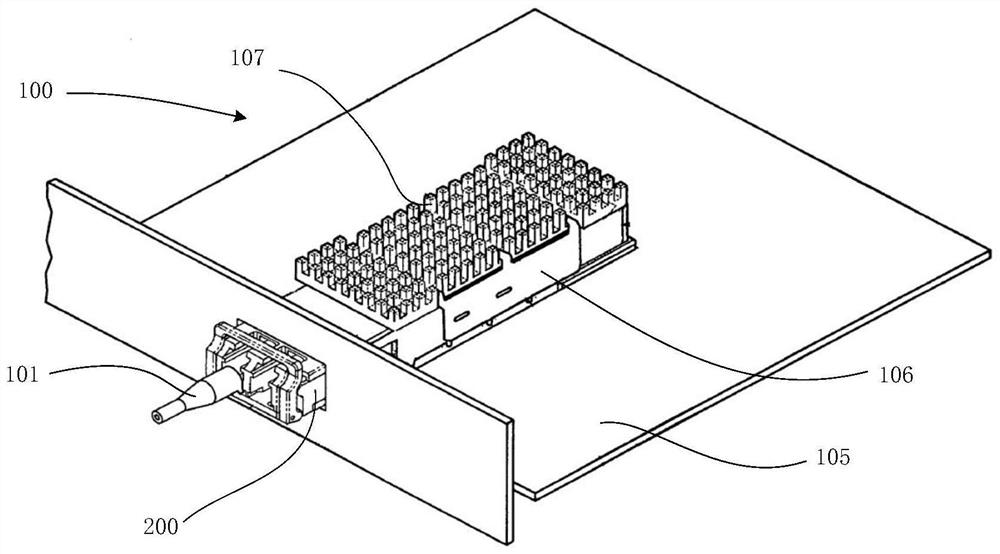
[0005] This application provides an optical module to solve the problems of insertion loss, chromatic aberration and poor structural compactness of the current lens-type optical module

Method used


Image

  • Optical module
  • Optical module
  • Optical module

Examples


Embodiment Construction

[0036] In order to enable those skilled in the art to better understand the technical solutions in the present application, the technical solutions in the embodiments of the present application will be clearly and completely described below in conjunction with the drawings in the embodiments of the present application. Obviously, the described The embodiments are only some of the embodiments of the present application, not all of them. Based on the embodiments in this application, all other embodiments obtained by persons of ordinary skill in the art without creative efforts shall fall within the scope of protection of this application.

[0037] One of the core links of optical fiber communication is the mutual conversion of optical and electrical signals. Optical fiber communication uses optical signals carrying information to be transmitted in information transmission equipment such as optical fibers / optical waveguides, and the passive transmission characteristics of light i...


PUM

PropertyMeasurementUnit
eccentricityaaaaaaaaaa

Abstract

The invention discloses an optical module, which comprises a circuit board and a light emitting assembly. The light emitting assembly comprises a laser which is electrically connected with the circuit board and used for emitting a Gaussian beam; a first off-axis parabolic reflector which is arranged on an emission light path of the laser located on the focus of the first off-axis parabolic reflector, has a first preset eccentricity with the laser, and is used for reflecting the Gaussian beam from the laser; a second off-axis parabolic mirror which is arranged on a reflection light path of the first off-axis parabolic mirror and is used for reflecting a collimated beam from the first off-axis parabolic mirror again; and a ferrule end face which is arranged on the focus of the second off-axis parabolic mirror, has a second preset eccentricity with the second off-axis parabolic mirror, and is used for receiving the beam reflected by the second off-axis parabolic mirror. According to the optical module, the off-axis parabolic mirrors instead of lenses are adopted, and the problems of insertion loss, color difference and poor structure compactness of a transmission-type optical module are solved.

Description

technical field [0001] The present application relates to the technical field of optical communication, and in particular to an optical module. Background technique [0002] The optical module is mainly used for photoelectric and electro-optical conversion. Its transmitting end converts electrical signals into optical signals and transmits them through optical fibers, and its receiving end converts received optical signals into electrical signals. Currently, the packaging forms of optical modules mainly include TO (Transistor-Outline, coaxial) packaging and COB (Chip on Board, chip-on-board) packaging. [0003] Currently TOSA (Transmitting Optical Sub-Assembly) or BOSA (Bi-Directional Optical Sub-Assembly) device optical module in TO package usually includes an optical transmitter and a coupling lens, and the optical transmitter emits The light beam is converged by the coupling lens, and finally coupled into the optical fiber, so that the electrical signal is converted into...

Claims


Application Information

Patent Timeline
Patent Type & Authority Applications(China)
IPC IPC(8): G02B6/42
CPCG02B6/4214G02B6/4204G02B6/428G02B6/4246
Inventor 黄绪杰葛建平张晓磊
Owner HISENSE BROADBAND MULTIMEDIA TECH
Learn More