Eureka AIR delivers breakthrough ideas for toughest innovation challenges, trusted by R&D personnel around the world.

Display device, drive circuit, testing device, and recording medium

Inactive Publication Date: 2007-06-19
SHARP KK
View PDF6 Cites 2 Cited by
  • Summary
  • Abstract
  • Description
  • Claims
  • Application Information

AI Technical Summary

Benefits of technology

[0011]An object of the preset invention is to provide a display device which can drastically reduce preparations for display test and a test device for the display device.
[0014]This makes it possible to carry out a display test using the test sequence and the testing patterns incorporated in the display device. Therefore, unlike the conventional testing device, there is no need to incorporate the test sequence and the testing patterns in the testing device.
[0015]Consequently, the display test for a display device with a large number of models requires no cumbersome and extensive tasks of preparing testing devices respectively corresponding to the models of the display device and a great number of complex data of the test sequence and the testing pattern which are respectively suitable for the models of the display device and storing them in the testing devices, respectively. That is, it is possible to drastically reduce preparations for a display test.
[0016]Note that, the test sequence and the testing patterns, grouped together in one testing program, can be stored in the nonvolatile memory. As to the testing pattern, image information with minimum unit (for example, 2×2 pixels) that has been stored in the nonvolatile memory is displayed on the display panel longitudinally and laterally in repeating fashion, thus realizing a small capacity of the nonvolatile memory.

Problems solved by technology

Moreover, the signal source device 80 had an intricate circuitry.
Therefore, a display test for a liquid crystal display device with a large number of models, such as mobile phone, required cumbersome and extensive works of preparing a great number of complex data of the test sequence and the testing pattern and storing them in a great number of signal source devices.

Method used


Image

  • Display device, drive circuit, testing device, and recording medium
  • Display device, drive circuit, testing device, and recording medium
  • Display device, drive circuit, testing device, and recording medium

Examples


first embodiment

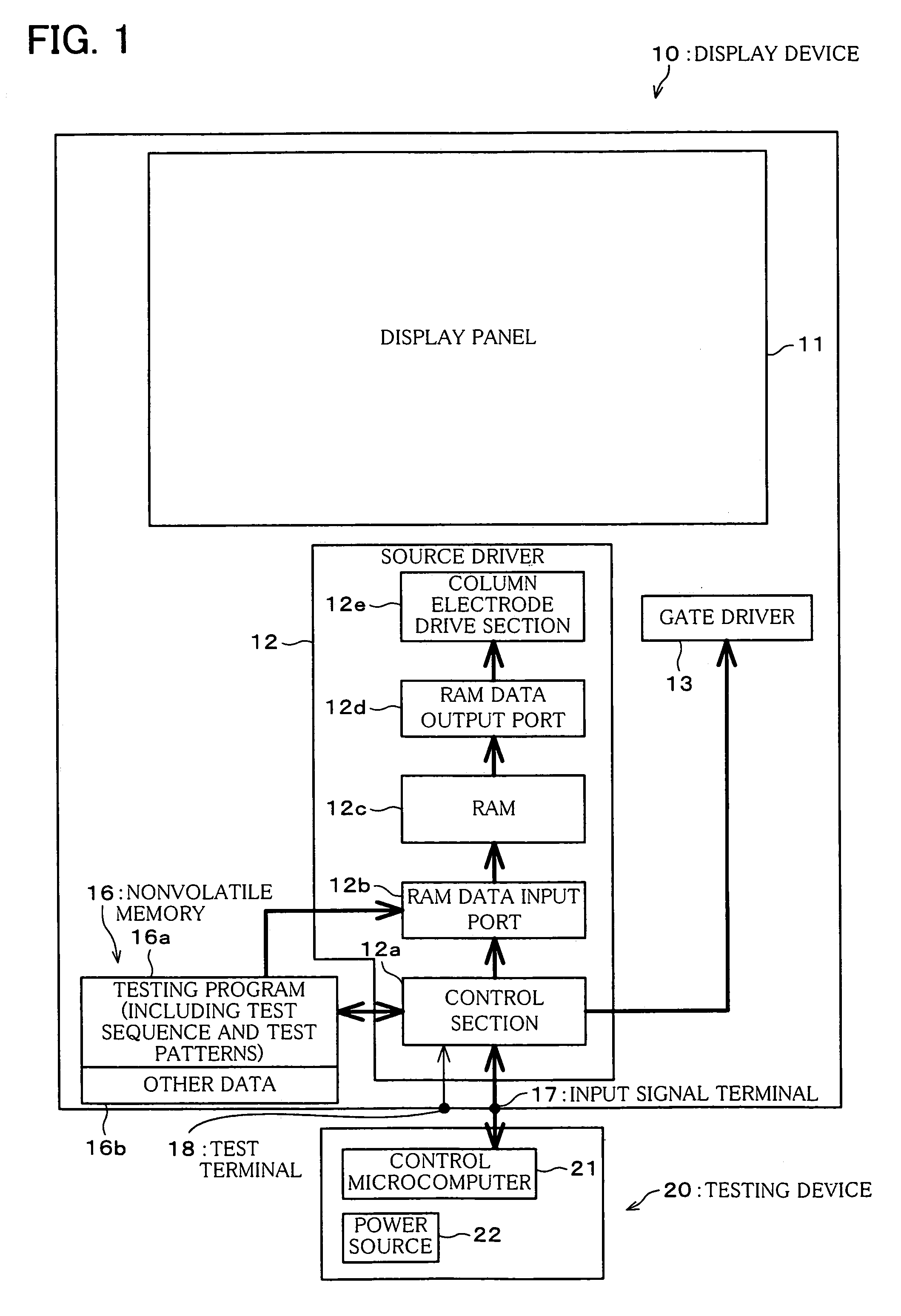
[0028]Referring to FIGS. 1 through 6, the following will describe one embodiment of the present invention.

[0029]As shown in FIG. 1, a display device 10 according to the present embodiment has a display panel (display means) 11 such as liquid crystal and includes a source driver (column electrode drive circuit) 12 and a gate driver (row electrode drive circuit, drive means) 13 both for driving the display panel 11. In addition, the display device 10 includes a nonvolatile memory (nonvolatile storage means) 16.

[0030]Further, in the display device 10, the source driver 12 includes a control section 12a, a RAM data input port (image data writing means) 12b, a RAM (random-access memory) 12c, a RAM data output port (image data reading means) 12d, and a column electrode drive section (drive means) 12e. Note that, the control section 12a, the RAM data input port 12b, the RAM 12c, and the RAM data output port 12d are equivalent to interface means.

[0031]The control section 12a is connected to...

second embodiment

[0061]The following will describe another embodiment of the present invention with reference to FIGS. 7 through 9 and FIGS. 2 through 6. Note that, for the purpose of explanation, members having the same functions as those described in the First Embodiment are given the same reference numerals and explanations thereof may be omitted here. The terms defined in the First Embodiment are also used as they are in the present embodiment unless otherwise specified.

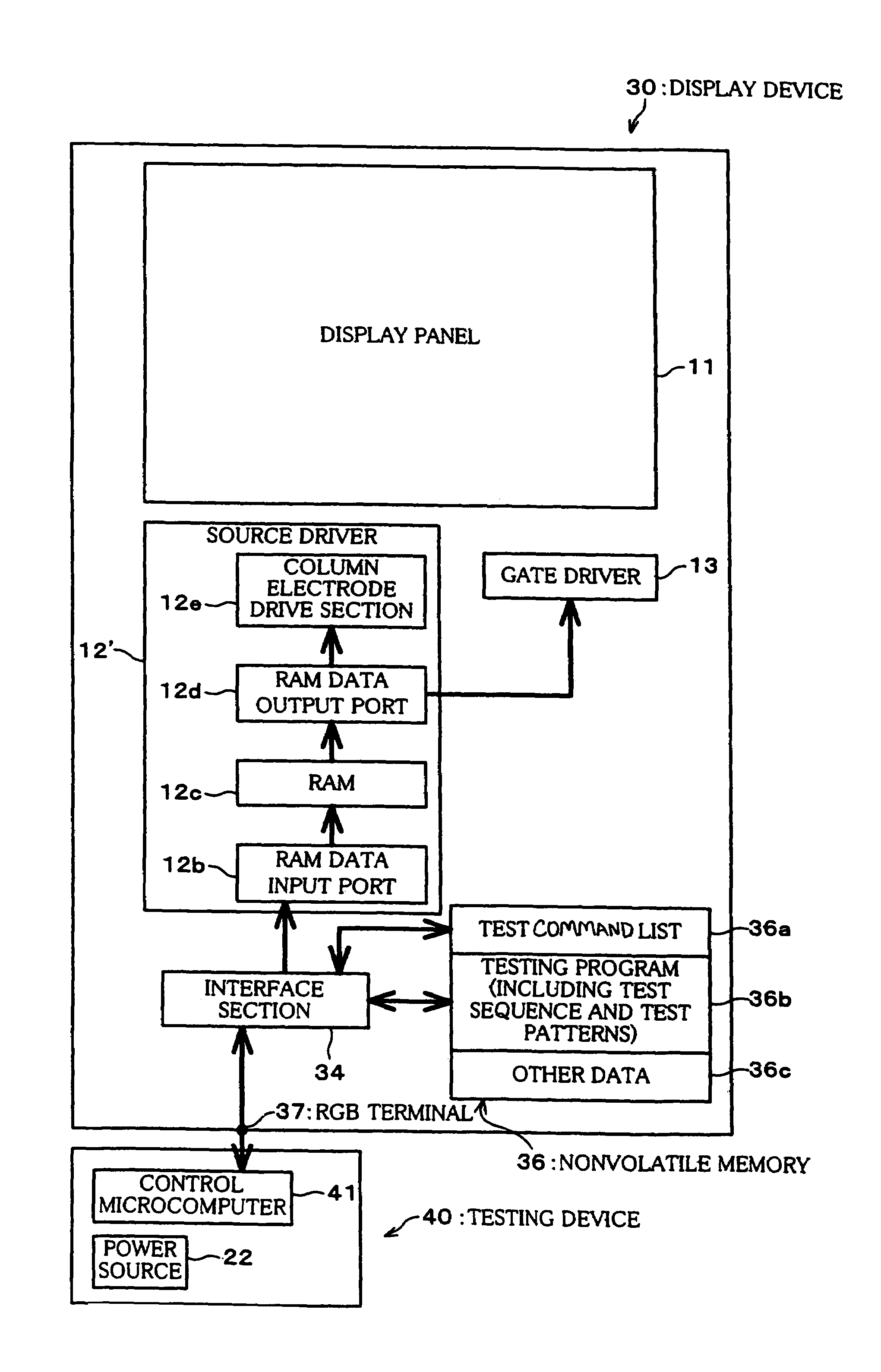
[0062]In a display device 30 according to the present embodiment, instead of the control section 12a and the nonvolatile memory 16 provided in the display device 10 of the First Embodiment (FIG. 1), an interface section (interface means) 34 and a nonvolatile memory 36 are provided. Therefore, the following will focus on the differences from the First Embodiment including the interface section 34 and the nonvolatile memory 36.

[0063]As shown in FIG. 7, the display device 30 has a display panel 11 such as liquid crystal and includes...


PUM


Abstract

A display device is provided with a display panel, and a source driver and a gate driver both for driving the display panel and includes a nonvolatile memory for storing a test sequence representing the procedures for a display test and testing patterns to be displayed in the display test and a control section for, in accordance with a test control signal supplied externally, controlling the source driver and the gate driver so as to display the testing patterns on the display panel in accordance with the test sequence. Since the test sequence and the testing patterns are stored in the nonvolatile memory of the display device, this eliminates the need for cumbersome and extensive tasks of preparing testing devices respectively corresponding to the models of the display device and a great number of complex data of the test sequence and the testing pattern which are respectively suitable for the models of the display device and storing them in the testing devices, respectively. That is, it is possible to drastically reduce preparations for a display test.

Description

FIELD OF THE INVENTION[0001]The present invention relates to a display device such as liquid crystal display device, more specifically, relates to a display device with the content of a display test varied depending on the model of the display device and a testing device for the display device.BACKGROUND OF THE INVENTION[0002]In a display test for the display devices including command interface, such as liquid crystal display device for mobile phone, a plurality of signal source devices for use in testing are needed for the reason of different command systems depending on users or for other reasons. In addition, a plurality of control programs for testing device must be prepared for the reason of different testing patterns to be displayed depending on users or for other reasons.[0003]As shown in FIG. 10, a conventional liquid crystal display device 70 has a display panel 71 and includes a source driver 72 and a gate driver 73 both for driving the display panel 71. Further, the sourc...

Claims


Application Information

Patent Timeline
IPC IPC(8): G09G5/00G09G3/36G02F1/13G09G3/00G09G3/20
CPCG09G3/006G09G3/36G02F1/13
Inventor SUGIYAMA, HIROAKINAKANO, TAKETOSHIYANAGI, TOSHIHIRO
Owner SHARP KK
Why Eureka
Eureka Blog
Learn More