TMR sensor

a sensor and tmr technology, applied in the field of sensors, can solve problems such as large resistance changes, and achieve the effect of maximizing miniaturization and accurately and precisely detecting mechanical values

Inactive Publication Date: 2007-06-26
STIFTUNG CAESAR +1
View PDF26 Cites 12 Cited by
  • Summary
  • Abstract
  • Description
  • Claims
  • Application Information

AI Technical Summary

Benefits of technology

The objective of this patent is to create a sensor that can accurately and precisely detect mechanical values, and that can be made smaller than current strain gauges or magneto-elastic sensors.

Problems solved by technology

The patent text discusses the use of magneto-resistance sensors in hard disk drives and the various configurations and materials used for the sensor. The technical problem addressed in the text is the need for improved sensors that can detect small changes in magnetic field and have higher sensitivity and accuracy. The text also mentions the use of tunnel magneto-resistance (TMR) elements in magnetic random access memory (MRAM) and the effect of mechanical stress on the sensor signal.

Method used


Image

  • TMR sensor
  • TMR sensor
  • TMR sensor

Examples


Embodiment Construction

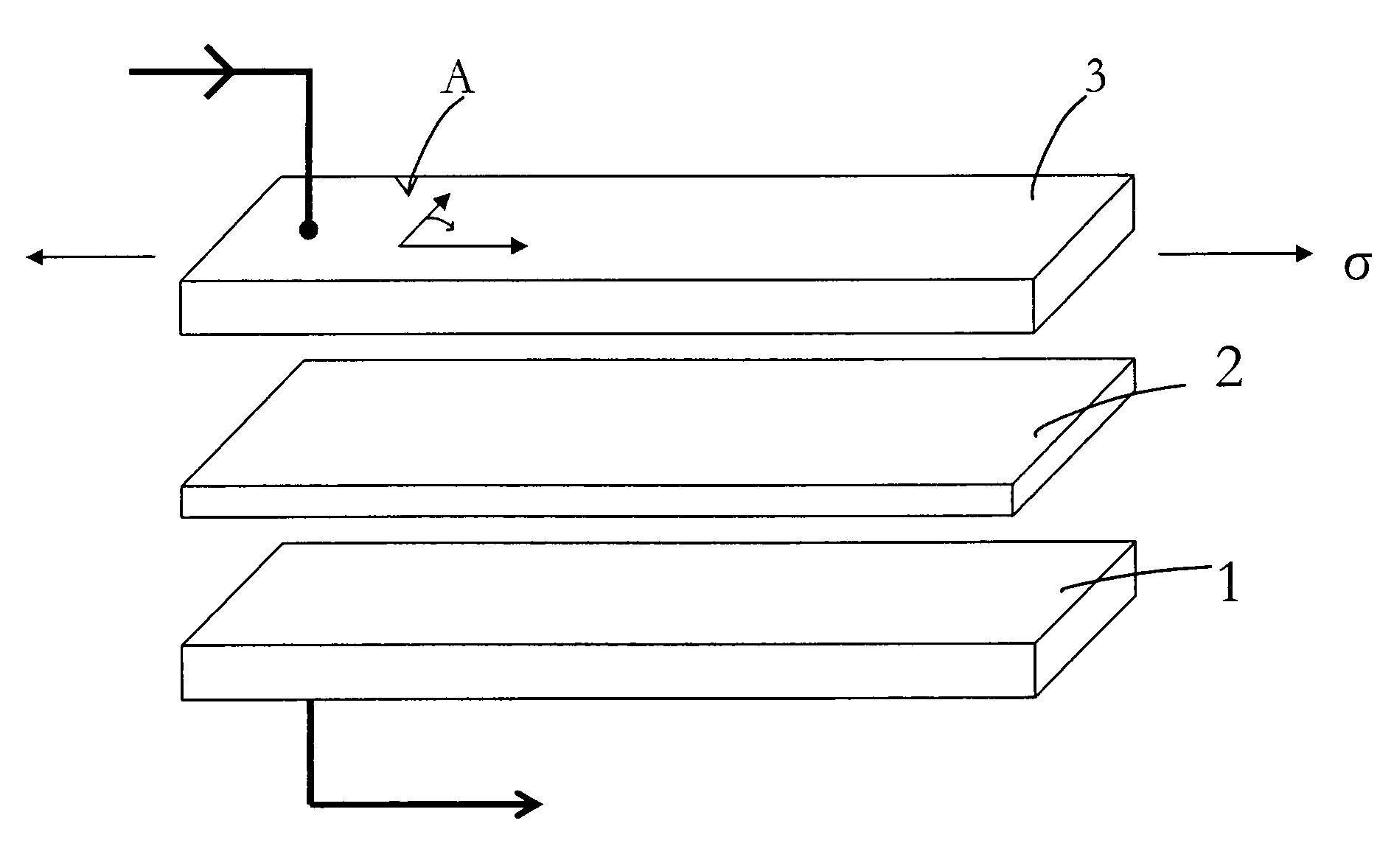
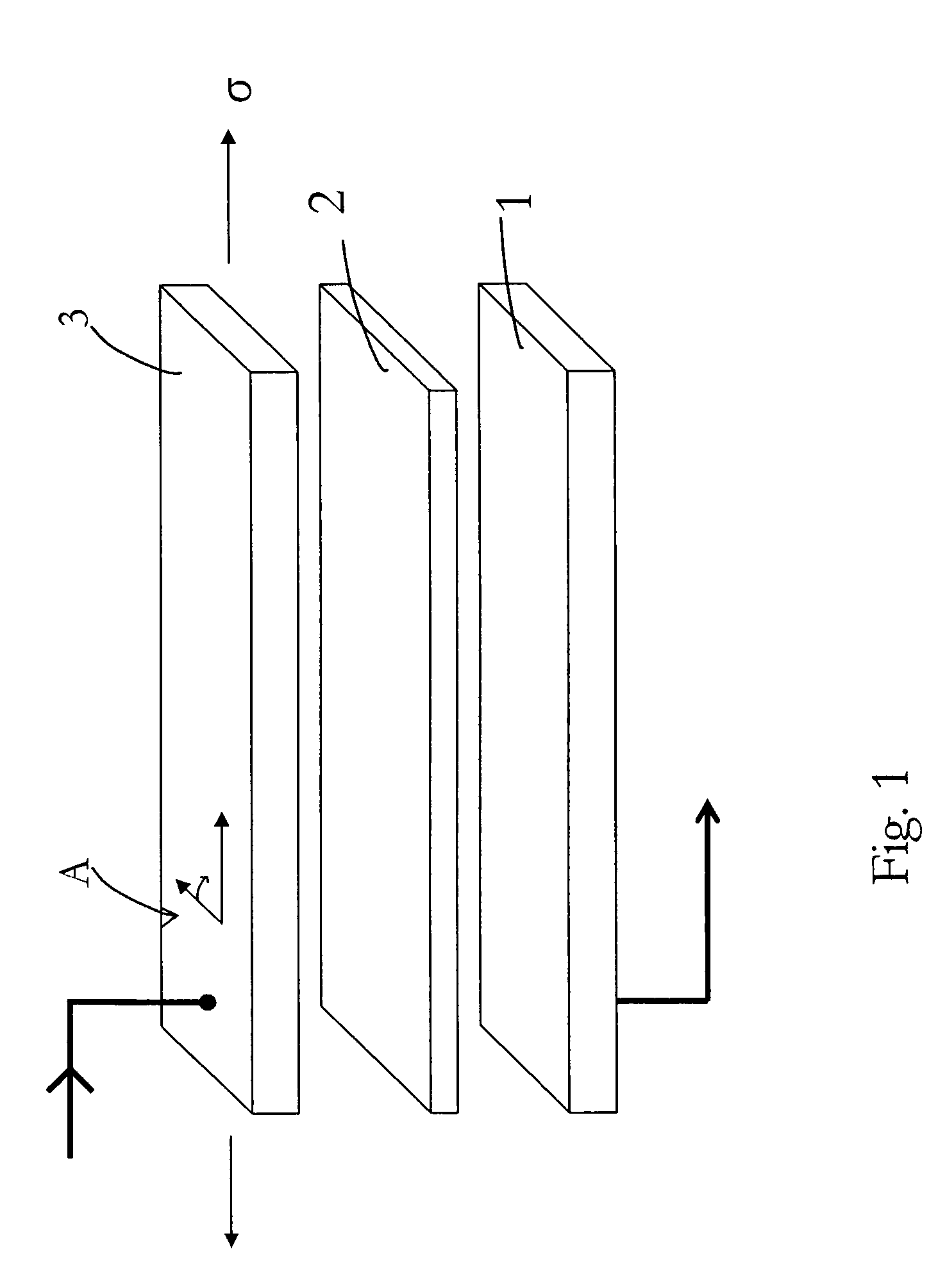
[0027]FIG. 1 is an exploded view of a magneto-elastic TMR sensor used to measure mechanical magnitudes. This sensor comprises a magnetically hard layer 1 which is separated by a tunnel barrier 2 from a magnetostrictive layer 3 which in particular may be an alloy containing CoFe. By applying an external mechanical stress (arrow σ), the direction of magnetization (arrow A) changes in the manner described above and thereby the resistance of the system crossed by the current I. Experiments carried out on such sensors with magnetically soft CoFe layers and amorphous (FeCo)SiB alloys are described below.

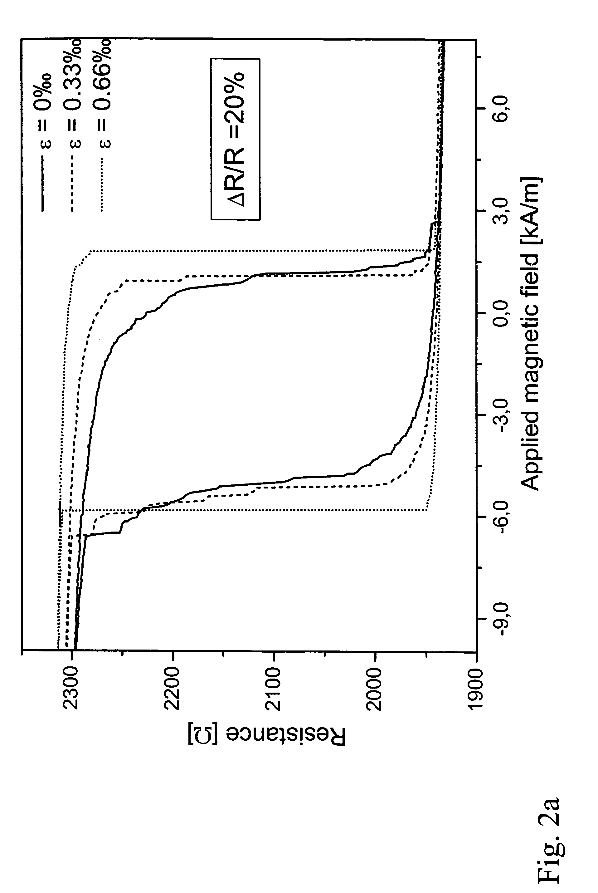
[0028]The magnetic tunnel elements are made by sputtering. The magnetically pinned layer consists in all samples of an 8 nm Ir23Mn77 antiferroamgnetic (AF) layer and of a 2.5 nm layer of Co—Fe. A 1.5 nm thick layer of aluminum is deposited as the tunnel barrier and is oxidized by plasma oxidation. Magnetostrictive Fe50Co50 and amorphous (Fe90Co10)78Si12B10 alloys nominally 6 nm thick are u...


PUM


Abstract

A sensor for measuring mechanical changes in length, in particular a compressive and/or tensile stress sensor, includes a sandwich system with two flat and superposed electrodes separated from each other by a tunnel element (tunnel barrier), in particular an oxide barrier, a current being set up between the electrodes and through the tunnel barrier, one electrode consisting of a magnetostrictive layer 3 which responds to elongation, and wherein the contributions of the anisotropies caused by mechanical tension are larger than those from the intrinsic anisotropies, relative changes in system resistance ΔR/R larger than 10% at room temperature being attained during elongation.

Description


Claims


Application Information

Patent Timeline
Owner STIFTUNG CAESAR
Why Eureka
Try Eureka