Medical implant with a communications interface

a technology of communication interface and medical implants, which is applied in the field of medical implants with communications interfaces, can solve the problems of limiting the possibility of miniaturizing such implants, and achieve the effect of improving the operation reliability of the implant and improving the safety of the implan

Inactive Publication Date: 2016-05-26
BIOTRONIK SE & CO KG
View PDF3 Cites 1 Cited by
  • Summary
  • Abstract
  • Description
  • Claims
  • Application Information

AI Technical Summary

Benefits of technology

[0025]In at least one embodiment, the adaptation sequence may be terminated by a quitting signal via the trigger element, or a safety setting may be activated with the absence of a quitting signal. As such, in one or more embodiments, the operational safety of the implant may be improved.
[0026]In...

Problems solved by technology

However, generally, the antenna's geometry significa...

Method used


Image

  • Medical implant with a communications interface
  • Medical implant with a communications interface
  • Medical implant with a communications interface

Examples


Embodiment Construction

[0032]The following description is of the best mode presently contemplated for carrying out at least one embodiment of the invention. This description is not to be taken in a limiting sense, but is made merely for the purpose of describing the general principles of the invention. The scope of the invention should be determined with reference to the claims.

[0033]In the drawings presented herein, functionally alike or similarly acting elements are denoted in each case by like reference signs. In addition, the drawings presented herein are schematic illustrations of the invention, and do not show specific parameters of the invention. Furthermore, the drawings presented herein merely reproduce one or more embodiments of the invention and are not intended to limit the invention to the illustrated embodiments.

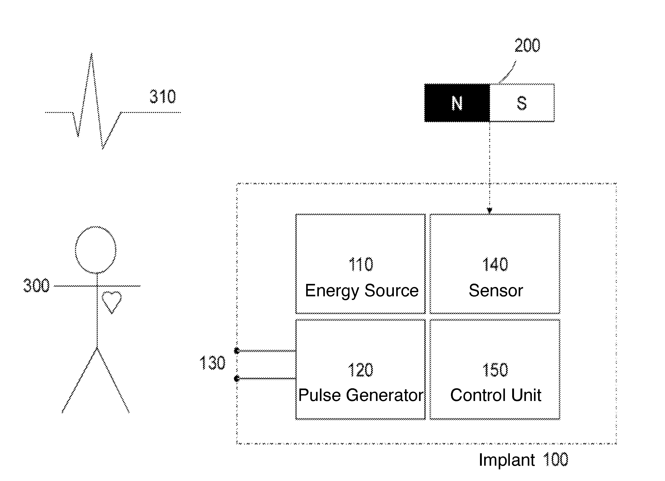
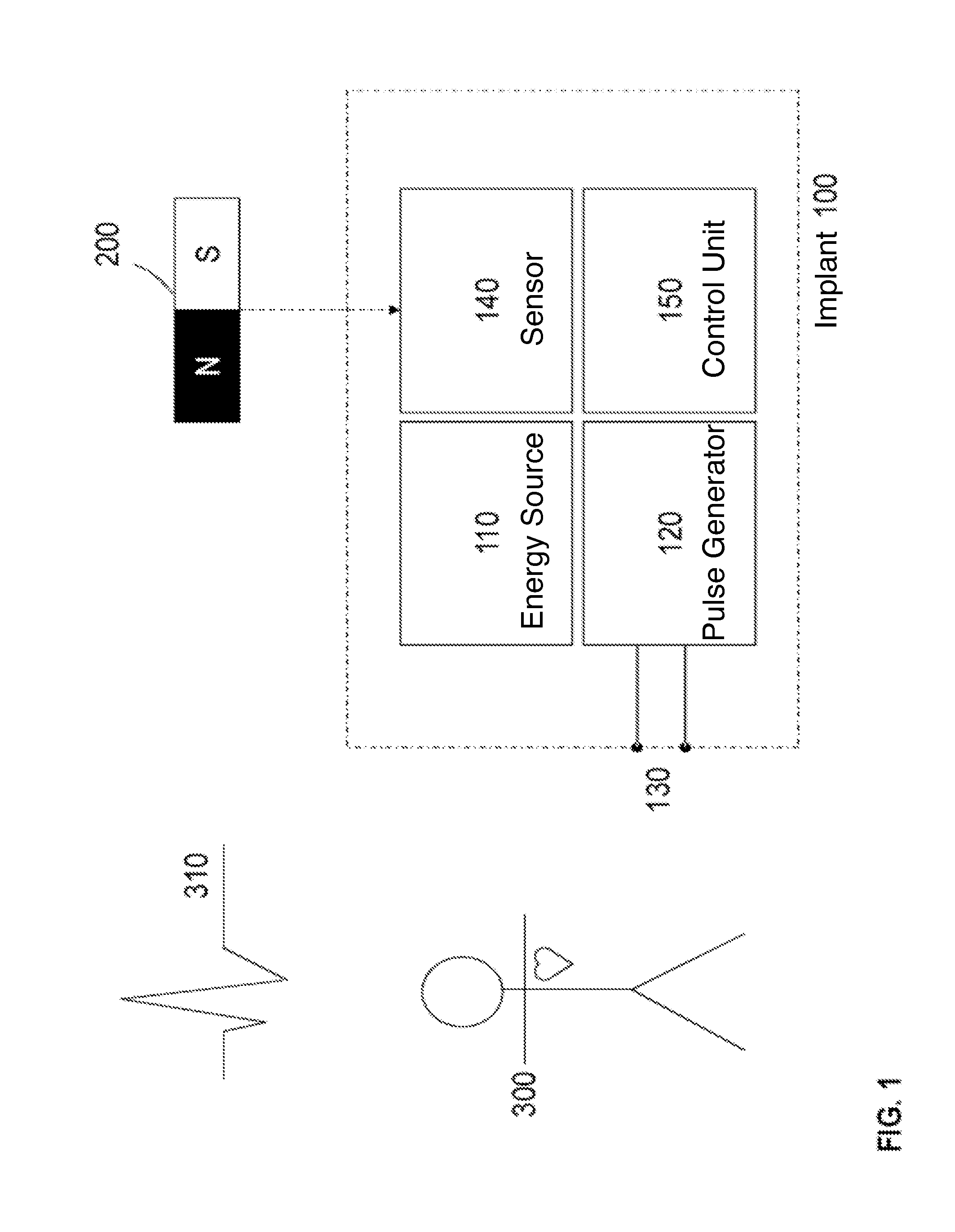
[0034]FIG. 1 shows a schematic illustration of a block diagram of an implant with an external trigger element, according to one or more embodiments of the invention. For example, FIG...


PUM


Abstract

Embodiments include a medical implant that is inserted into a human and/or animal body. The medical implant includes an energy source, a pulse generator, a control unit and at least one electrode pair that delivers electrical stimulation pulses to a bodily tissue. Embodiments include a sensor, provided on an implant side of the medical implant, that identifies an implant-external trigger element. The control unit is coupled to the sensor and may be activated depending on a sensor signal of the sensor to perform an adaptation sequence of stimulation parameters, in which test stimulation pulses may be outputted. Embodiments include a method of setting a parameter set of therapeutic electrical stimulation pulses of a medical implant.

Description

[0001]This application claims the benefit of U.S. Provisional Patent Application 62 / 083,899 filed on 25 Nov. 2014, the specification of which is hereby incorporated herein by reference.BACKGROUND OF THE INVENTION[0002]1. Field of the Invention[0003]Embodiments of the invention generally relate to a medical implant with a communications interface.[0004]2. Description of the Related Art[0005]Generally, active electronic implants for insertion into the human and / or animal body have a bidirectional communications interface for a telemetry function to be able to set stimulation parameters. Typically, the telemetry function of the active electronic implant requires an antenna that is suitable for telemetry and which is adapted to the frequency to be used. However, generally, the antenna's geometry significantly limits the possibility of miniaturizing such implants.BRIEF SUMMARY OF THE INVENTION[0006]One or more embodiments of the invention provide an implant with telemetry possibilities, ...

Claims


Application Information

Patent Timeline
IPC IPC(8): A61N1/372A61N1/39A61N1/378A61N1/375A61N1/36A61N1/365
CPCA61N1/37241A61N1/36003A61N1/36135A61N1/3987A61N1/378A61N1/3756A61N1/365A61N1/371A61N1/37217A61N1/37247A61B2017/00119A61B2017/00876A61B2562/0223A61B5/304
Inventor DOERR, THOMASDIEBOLD, MICHAEL
Owner BIOTRONIK SE & CO KG
Why Eureka
Try Eureka