Subsea chemical injection unit for additive injection and monitoring system for oilfield operations

a technology of additive injection and monitoring system, applied in the field of oilfield operations, can solve problems such as reducing the effectiveness of additive injection process, and achieve the effects of preventing or reducing the buildup of harmful elements, promoting separation and/or processing of formation fluids, and preventing or reducing corrosion of hardwar

Inactive Publication Date: 2007-06-26
BAKER HUGHES INC
View PDF27 Cites 103 Cited by
  • Summary
  • Abstract
  • Description
  • Claims
  • Application Information

AI Technical Summary

Benefits of technology

[0009]This invention provides a system and method for deployment of chemicals or additives in subsea oilwell operations. The chemicals used prevent or reduce build up of harmful elements, such as paraffin or scale and prevent or reduce corrosion of hardware in the wellbore and at the seabed, including pipes and also promote separation and / or processing of formation fluids produced by subsea wellbores. In one aspect, the system includes one or more subsea mounted tanks for storing chemicals, one or more subsea pumping systems for injecting or pumping chemicals into one or more wellbores and / or subsea processing units(s), a system for supplying chemicals to the subsea tanks, which may be via an umbilical interfacing the subsea tanks to a surface chemical supply unit or a remotely-controlled unit or vehicle that can either replace the empty subsea tanks with chemical filled tanks or fill the subsea tanks with the chemicals. The subsea tanks may also be replaced by any other conventional methods. The surface and subsea tanks may include multiple compartments or separate tanks to hold different chemicals which can be deployed into wellbores at different or same time. The subsea chemical injection unit can be sealed in a water-tight enclosure. The subsea chemical storage and injection system decreases the viscosity problems related to pumping chemicals from the surface through umbilical capillary tubings to a subsea installation location that may in some cases be up to 20 miles from the surface pumping station.

Problems solved by technology

The distance separating the chemical injection unit and the locus of injection activity can reduce the effectiveness of the additive injection process.

Method used


Image

  • Subsea chemical injection unit for additive injection and monitoring system for oilfield operations
  • Subsea chemical injection unit for additive injection and monitoring system for oilfield operations
  • Subsea chemical injection unit for additive injection and monitoring system for oilfield operations

Examples


Embodiment Construction

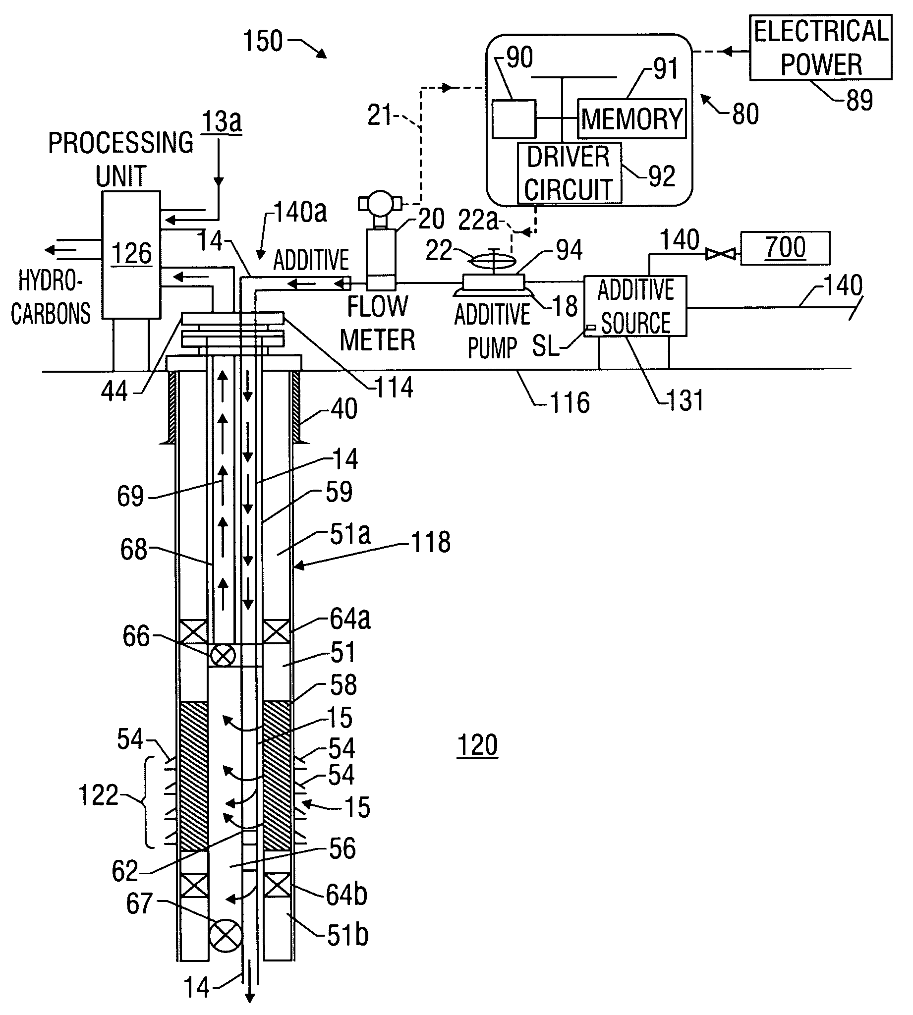
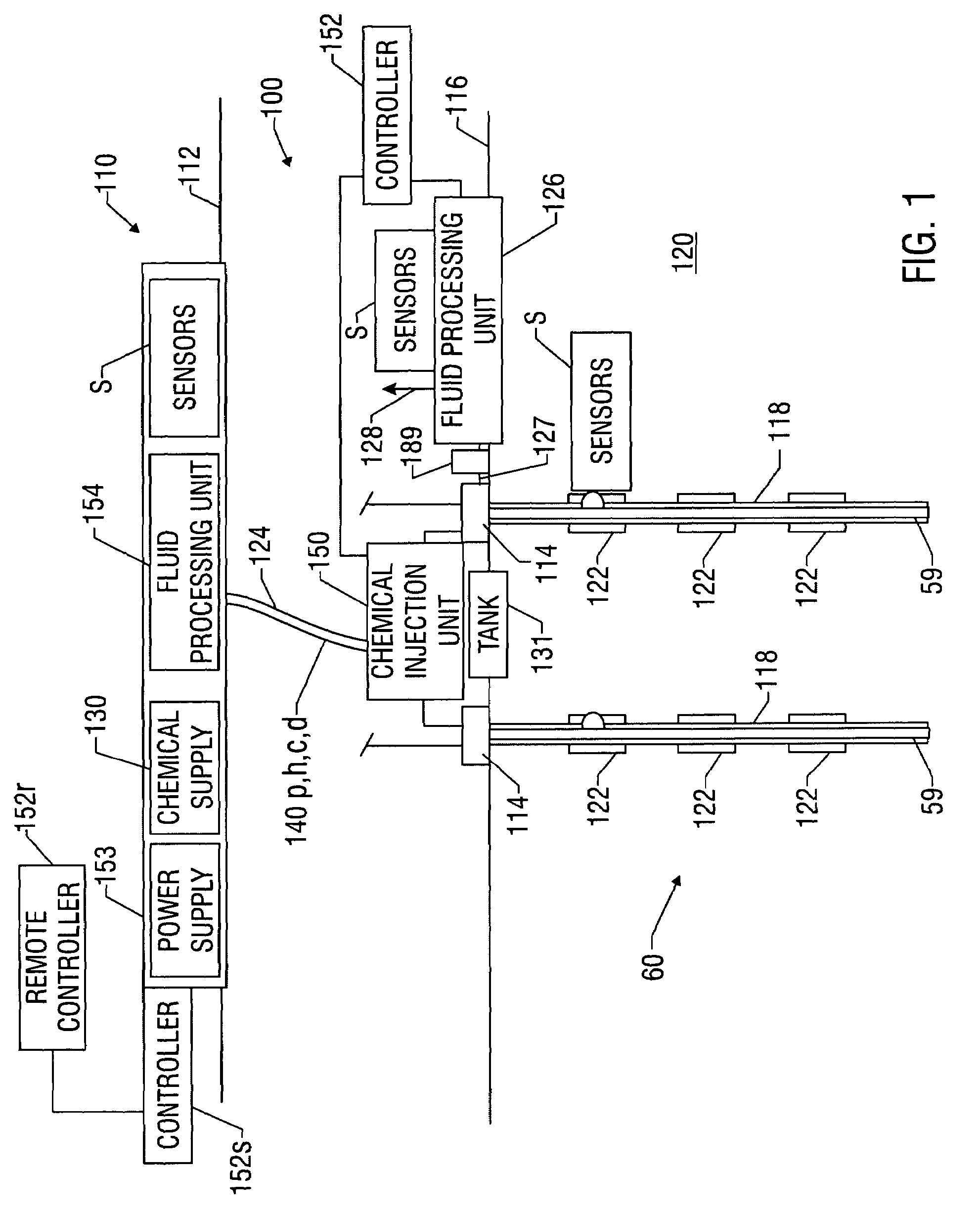
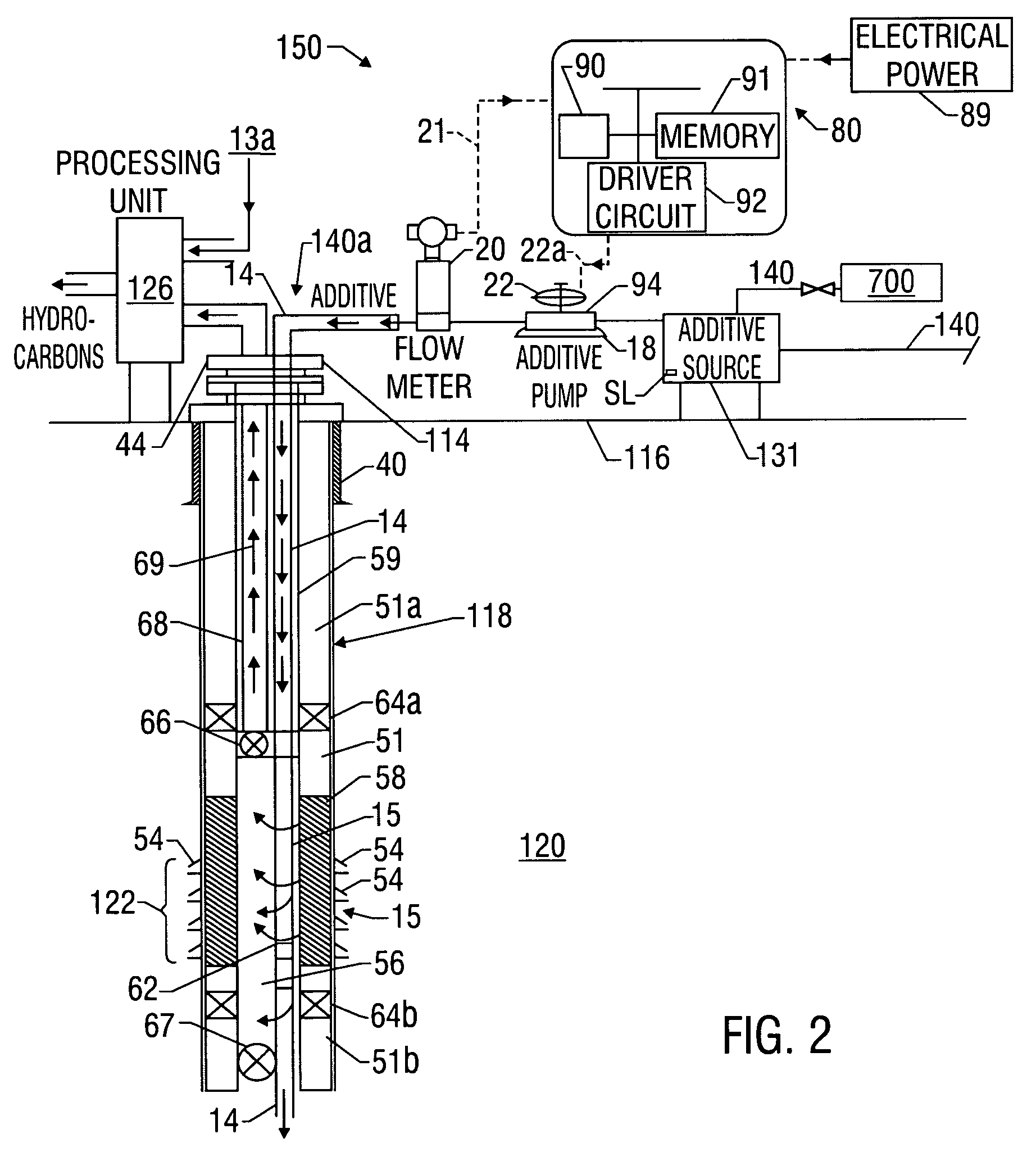
[0026]Referring initially to FIG. 1, there is schematically shown a chemical injection and monitoring system 100 (hereafter “system 100”) made in accordance with the present invention. The system 100 may be deployed in conjunction with a surface facility 110 located at a water's surface 112 that services one or more subsea production wells 60 residing in a seabed 116. Conventionally, each well 60 includes a well head 114 and related equipment positioned over a wellbore 118 formed in a subterranean formation 120. The well bores 118 can have one or more production zones 122 for draining hydrocarbons from the formation 120 (“produced fluids” or “production fluid”). The production fluid is conveyed to a surface collection facility (e.g., surface facility 110 or separate structure) or a subsea collection and / or processing facility 126 via a line 127. The fluid may be conveyed to the surface facility 110-via a line 128 in an untreated state or, preferably, after being processed, at least ...


PUM


Abstract

A system monitors and controls the injection of additives into formation fluids recovered through a subsea well. The system includes a chemical injection unit and a controller positioned at a remote subsea location. The injection unit uses a pump to supply one or more selected additives from a subsea and / or remote supply unit. The controller operates the pump to control the additive flow rate based on signals provided by sensors measuring a parameter of interest. A one mode system includes a surface facility for supporting the subsea chemical injection and monitoring activities. In one embodiment, the surface facility is an offshore rig that provides power and has a chemical supply that provides additives to one or more injection units. In another embodiment, the surface facility includes a relatively stationary buoy and a mobile service vessel. When needed, the service vessel transfers additives to the chemical injection units via the buoy.

Description

CROSS-REFERENCE TO RELATED APPLICATIONS[0001]This application takes priority from U.S. Provisional Application Ser. No. 60 / 403,445 filed Aug. 14, 2002.BACKGROUND OF THE INVENTION[0002]1. Field of the Invention[0003]This invention relates generally to oilfield operations and more particularly to a subsea chemical injection and fluid processing systems and methods.[0004]2. Background of the Art[0005]Conventional offshore production facilities often have a floating or fixed platforms stationed at the water's surface and subsea equipment such as a well head positioned over the subsea wells at the mud line of a seabed. The production wells drilled in a subsea formation typically produce fluids (which can include one or more of oil, gas and water) to the subsea well head. This fluid (wellbore fluid) is carried to the platform via a riser or to a subsea fluid separation unit for processing. Often, a variety of chemicals (also referred to herein as “additives”) are introduced into these pro...

Claims


Application Information

Patent Timeline
Patent Type & Authority Patents(United States)
IPC IPC(8): E21B37/06E21B43/01E21B41/02
CPCE21B37/06E21B41/02
Inventor SHAW, CHRISTOPHER KEMPSONCROW, CINDY L.AESCHBACHER, JR., WILLIAM EDWARDRAMACHANDRAN, SUNDERMEANS, MITCH C.TUBEL, PAULO S.
Owner BAKER HUGHES INC
Why Eureka
Try Eureka