Amphibious vehicle suspension

a suspension and amphibious technology, applied in the field of vehicle suspension, can solve the problems of wheel recesses, slow or slew the vehicle, different opportunities and challenges,

Active Publication Date: 2007-06-26
GIBBS TECH
View PDF17 Cites 18 Cited by
  • Summary
  • Abstract
  • Description
  • Claims
  • Application Information

AI Technical Summary

Benefits of technology

[0012]To reduce the bulk of the suspension recesses in the hull, the spring and damper units for each road wheel may be mounted remotely from the upper and lower suspension members; preferably within a watertight interior compartment of the vehicle. The road wheel suspension retraction and protraction means may similarly be mounted remotely from the wheel suspension. Clearly both spring and damper units and retraction and protraction means must be mechanically linked to the upper and lower suspension members. The retraction and protraction means may be linked to a pivotal arm, to either end of which are mounted springs and dampers. The cage means may be sealed against ingress of water.

Problems solved by technology

Nevertheless, tramping caused by hitting waves or wakes; or alternatively cornering; can cause the wheel recesses to catch the water, which may in turn slow or slew the vehicle.
However, if alternative packaging concepts from lighter and more compact vehicles are considered, different opportunities and challenges arise.
The large vee angle offers agile marine handling, but requires the use of large diameter road wheels to give adequate ground clearance; which would suggest large wheel arches and bulky suspension.
Should these large wheel arches be integrated into the vehicle body styling, they would tend to negate the compactness and light weight of a narrow amphibious vehicle.
However, if the wheel arches are allowed to protrude beyond the contours of the rest of the vehicle bodywork, the main structure of the vehicle can still be narrow and light in weight.

Method used


Image

  • Amphibious vehicle suspension
  • Amphibious vehicle suspension
  • Amphibious vehicle suspension

Examples


Embodiment Construction

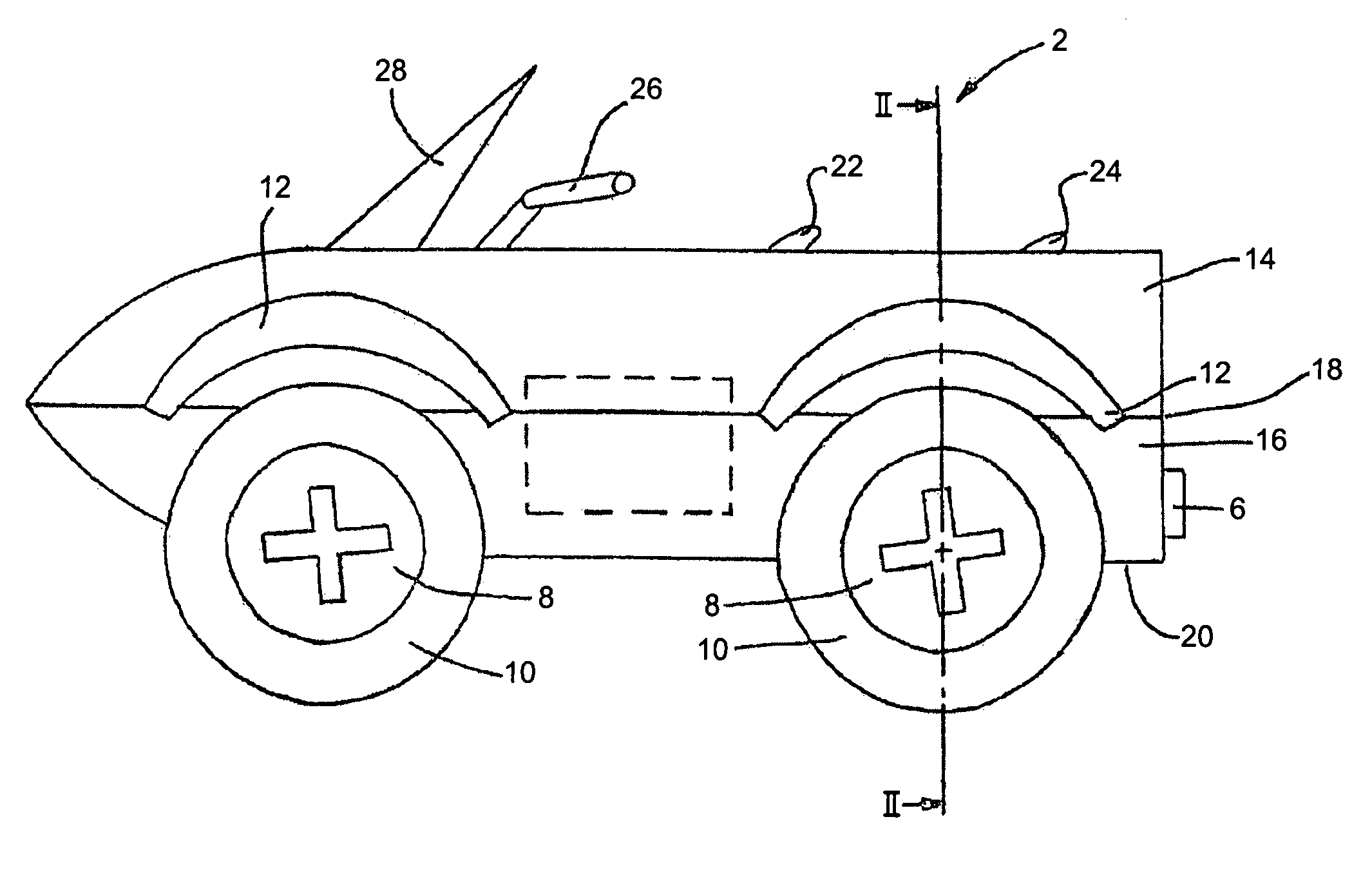
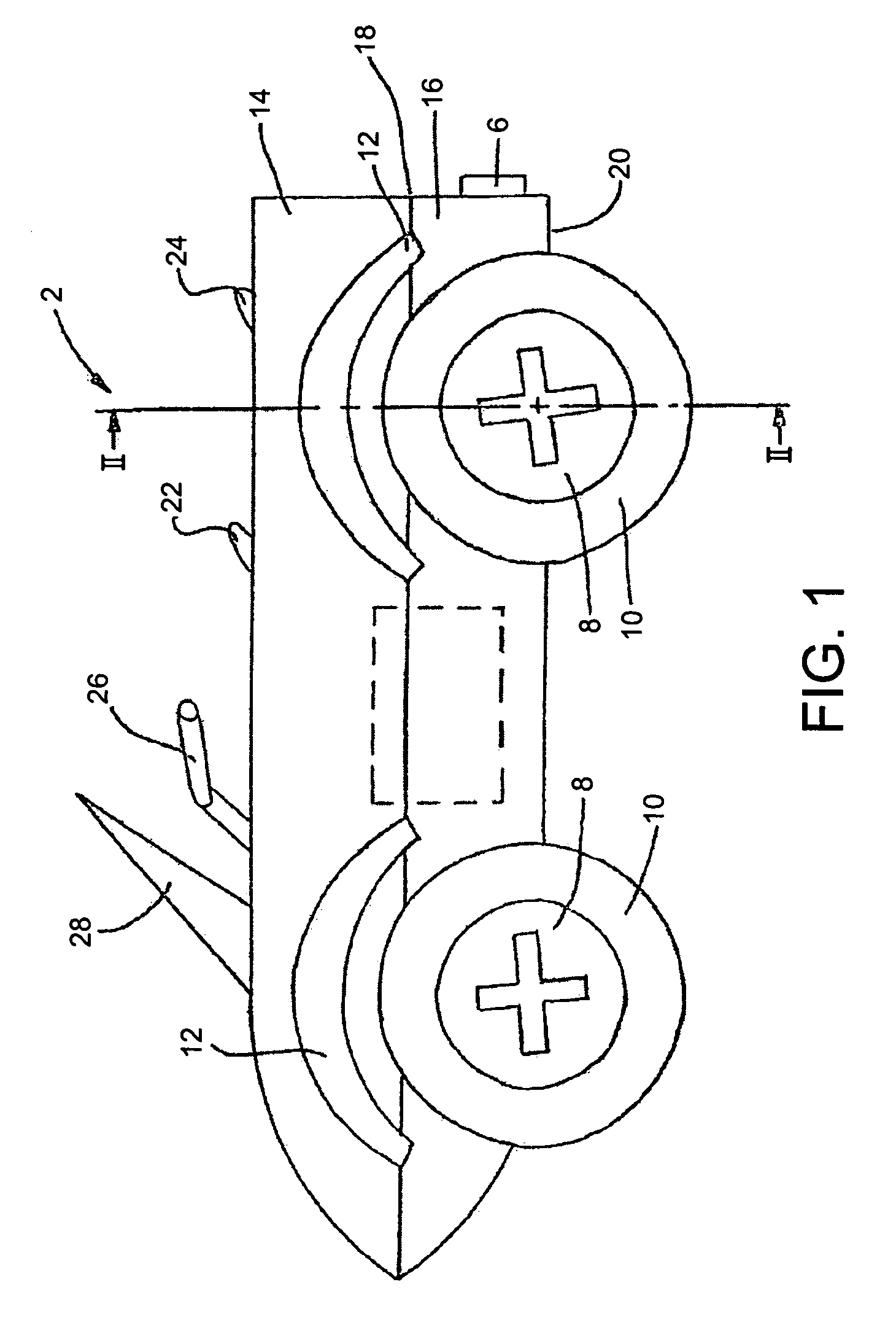
[0022]Amphibious vehicle 2 comprises prime mover 4 driving marine drive means 6 through a marine transmission (not shown). Drive means 6 may be a jet. Locomotion on road is provided by wheels 8 and tyres 10, which are driven through a road transmission (not shown). The wheels and tyres are shielded by wheel arches 12. Body 14 and hull 16 may be formed separately and joined at split line 18. The hull may have a planing surface 20. At least a driver's seat 22 is provided; one or more passenger seats 24 may be provided astern of the driver's seat. The seating axis may be on the longitudinal axis of the vehicle, or parallel thereto. The axis of the prime mover may also be along, or parallel to, the longitudinal axis of the vehicle. Driver controls are provided, such as handlebars 26. A windscreen 28 may be provided for weather and spray protection. Spray management features (not shown) may also be built into the hull, along with a keel and strake(s).

[0023]An advantage of a split hull / bo...


PUM


Abstract

A retractable suspension for an amphibious vehicle, the configuration of which allows the size of an opening in the hull necessary for accommodating the protraction of each wheel to be kept to a minimum. The suspension is configured such that the only component that comes to extend beyond the hull upon protraction is a generally tube shaped lower link that is pivotally attached to the hull at it is inboard end, that pivotally supports a hub carrier at its outboard end and that may simultaneously accommodate a drive shaft therein. The weight of the vehicle is supported by a spring arrangement bearing on the inboard end of the lower link.

Description

CROSS-REFERENCES TO RELATED APPLICATIONS[0001]This application claims priority from Great Britain Application Serial No. 0423463.9, filed Oct. 22, 2004.BACKGROUND OF THE INVENTION[0002]The present invention relates to vehicle suspension for driven axles of amphibious vehicles.[0003]In an amphibious vehicle, it is desirable to reduce drag when in marine mode, particularly drag caused by disconformities in those parts of the vehicle in contact with the water. Some such vehicles have retracting wheels with recesses above the water-line for the wheels to retract into. In the case of a planing amphibious vehicle, the hull recesses are generally above the water-line when the vehicle is on the plane; or in the case of our co-pending application no. WO 04 / 103743A1, plates are fitted to the vehicle's bottom to cover as much as possible of the recesses for the rear driven wheels. Such plates are fixed after assembly of the vehicle suspension during manufacture. Nevertheless, tramping caused b...

Claims


Application Information

Patent Timeline
Patent Type & Authority Patents(United States)
IPC IPC(8): B60F3/00B60G3/20
CPCB60F3/0007B60G3/20B60F2301/04B60G2200/144B60G2204/421B60G2204/47B60G2300/28
Inventor LONGDILL, SIMON JAMESWEEKERS, HANSBRIGGS, STEPHEN JOHN
Owner GIBBS TECH
Why Eureka
Try Eureka