Method of improving pedicle screw placement in spinal surgery

a technology of pedicle screw and spinal surgery, applied in the field of spinal surgery, can solve the problems of biomechanical inferior construction, no system available to automatically determine the ideal pedicle screw placement, and significant morbidity and/or mortality, and achieve the effect of convenient safe and reliable access

Active Publication Date: 2007-06-26
LEUCADIA 6 LLC
View PDF44 Cites 88 Cited by
  • Summary
  • Abstract
  • Description
  • Claims
  • Application Information

AI Technical Summary

Benefits of technology

[0008]The invention also facilitates safe and reliable access to any vertebral body through a transpedicular or peripedicular approach, such as during a vertebroplasty, kyphoplasty or vertebral body biopsy.

Problems solved by technology

However, adjacent to the spine are numerous vital structures and organs, in particular the cervical and thoracic spine regions, which have very low tolerance for surgically created injuries that may ultimately lead to significant morbidity and / or mortality.
Up to the present time, no system is available which will automatically determine ideal pedicle screw diameter, length and trajectory for accurate placement of pedicle screws.
A disadvantage of this method is that it allows for eccentric trajectory determination, particularly for distorted pedicle anatomy, with consequent smaller maximum diameter and length screw determinations resulting in biomechanically inferior constructions.

Method used


Image

  • Method of improving pedicle screw placement in spinal surgery
  • Method of improving pedicle screw placement in spinal surgery
  • Method of improving pedicle screw placement in spinal surgery

Examples


Embodiment Construction

[0058]The methods of determining pedicle screw size and placement in accordance with the present invention are set forth in more detail hereinafter.

Step 1

[0059]A computed tomography scan (CT), magnetic resonance image (MRI), CT capable fluoroscopy or similar two-dimensional imaging study of the spine area of interest may first be obtained. Thin cut sections are preferable to increase accuracy and detail.

Step 2

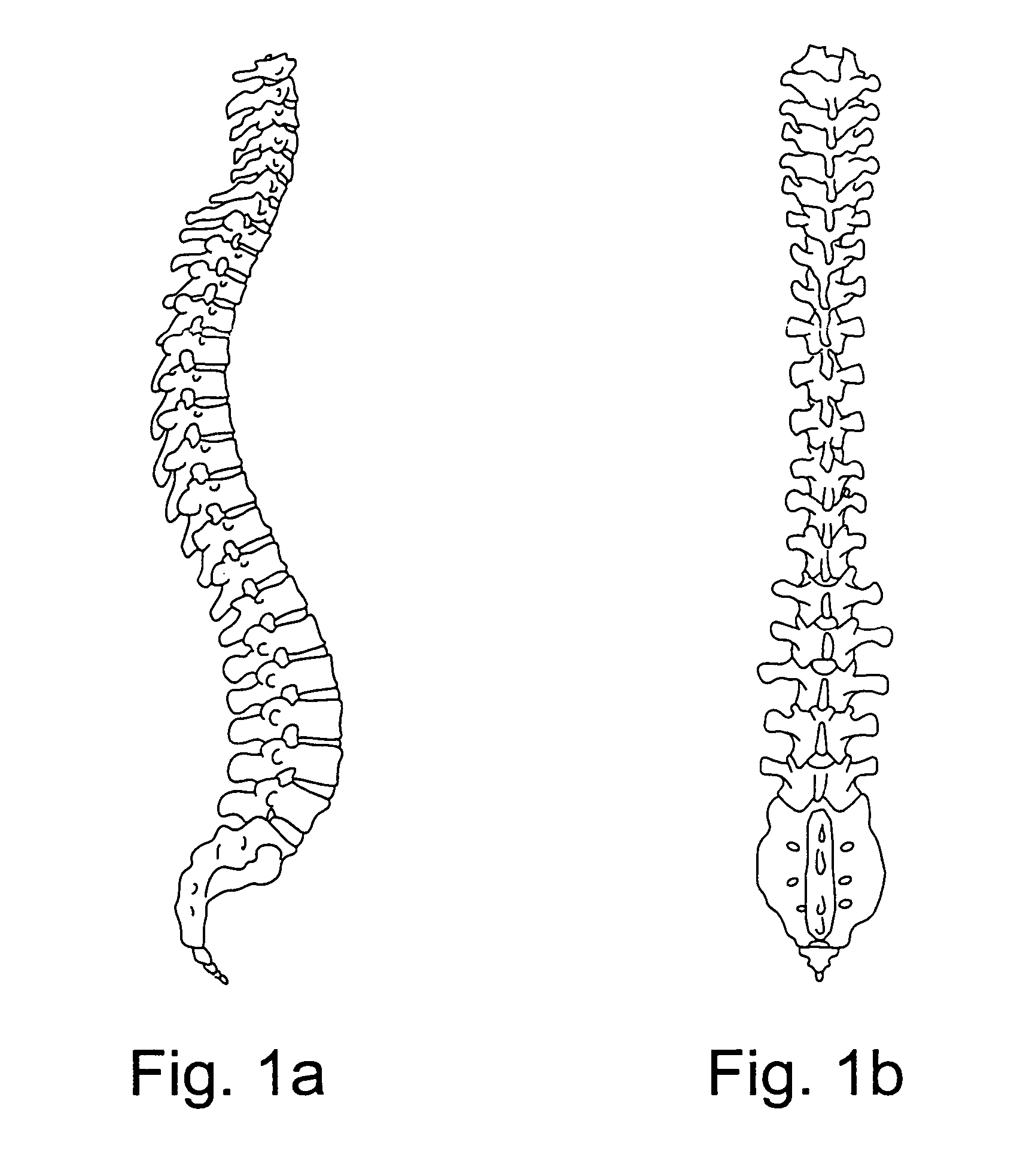
[0060]A dimensionally true three dimensional computer image of the bony spine is made from the CT, MRI or other studies or in any other suitable manner, as shown in FIGS. 1a and 1b.

Step 3

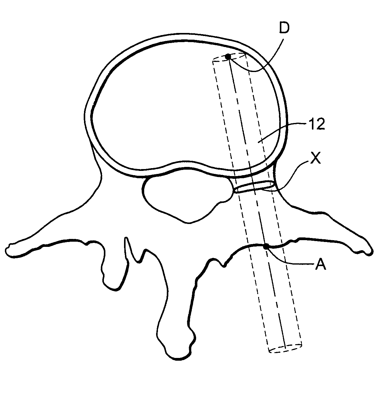
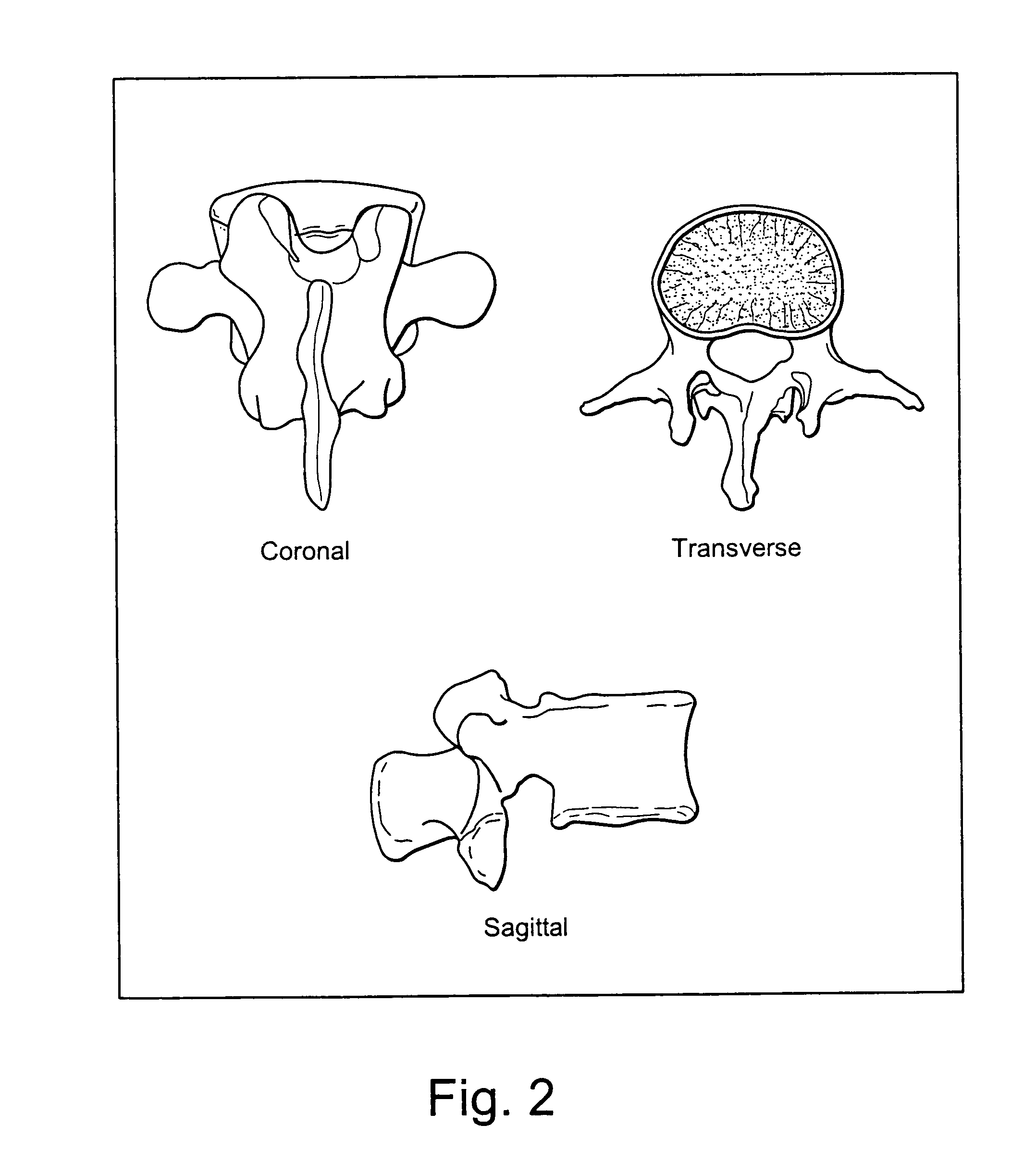
[0061]The three dimensional individual vertebra as shown in FIG. 2 are then hollowed out by a computer, similar to an eggshell transpedicular vertebral corpectomy, to the specifications desired by the surgeon (i.e., thickness of cortical wall remaining in the vertebral body cortices or pedicle walls). These specifications allow for asymmetric thicknesses, such that, for example, anterior verte...


PUM


Abstract

A method of determining the size and trajectory of screws in pedicles during surgery, comprising generating a three-dimensional image of the bony spine; hollowing out the vertebra in the image with cortical wall thicknesses selected by a surgeon; determining the isthmus within each pedicle; generating a straight line starting at the center of the isthmus and extending in opposite directions so that it is positioned concentrically within the pedicle without touching the walls thereof, the line terminating inside the vertebral body a predetermined distance from the anterior inner cortical wall and extending outwardly in the opposite direction to penetrate the posterior pedicle cortex; expanding the line concentrically and radially to a cross sectional size that is less than that of the isthmus, the line being expanded into a cylinder that stops growing when any portion thereof contacts the inner cortical wall of the hollowed out vertebral body; and calculating pedicle screw size and trajectory based on the cylinder.

Description

[0001]This application claims the benefit of U.S. Provisional Patent Application No. 60 / 545,903, filed on Feb. 20, 2004.FIELD OF THE INVENTION[0002]The present invention relates to the general field of spinal surgery and, more particularly, to a computerized or automated method for the accurate sizing and placement of pedicle screws in spinal surgery.BACKGROUND OF THE INVENTION[0003]Placement of screws into the human spine is a common surgical procedure to allow for a multitude of spinal surgeries to be performed. Screws are typically placed into the pedicles of individual vertebra in the lumbar and sacral spine. Given their biomechanical advantages over other modes of fixation, surgeons are expanding the areas of the spine in which pedicle screws are placed. However, adjacent to the spine are numerous vital structures and organs, in particular the cervical and thoracic spine regions, which have very low tolerance for surgically created injuries that may ultimately lead to significa...

Claims


Application Information

Patent Timeline
Patent Type & Authority Patents(United States)
IPC IPC(8): A61B17/56A61B17/16A61B17/17A61B17/88A61B19/00A61F2/30
CPCA61B17/1757A61B17/1671A61B17/1604A61B17/1615A61B2019/5238A61B19/50A61B2090/376A61B34/10A61B17/56A61B17/68A61B17/88A61B17/70
Inventor PACHECO, HECTOR O.
Owner LEUCADIA 6 LLC
Why Eureka
Try Eureka