Arc resistant switchgear having dedicated vertical plenums

a technology of switchgear and vertical plenum, which is applied in the direction of electrical apparatus construction details, non-enclosed substations, etc., can solve the problems of reducing the ability of the air inside the switchgear to provide the previous insulative capabilities, severe mechanical and thermal stress on the equipment, and many undesirable events, so as to reduce the pressure within the switchgear assembly and quickly dissipate the exhaust

Active Publication Date: 2007-06-26
PACS SWITCHGEAR LLC
View PDF10 Cites 41 Cited by
  • Summary
  • Abstract
  • Description
  • Claims
  • Application Information

AI Technical Summary

Benefits of technology

[0023]The primary objective of this invention is to provide switchgear that can quickly dissipate the exhaust from an explosion due to electrical arcing within a switchgear assembly without possibly spreading the explosive detritus, smoke, or airborne chemicals to adjacent vertical cubicles as can occur in switchgear having an internal horizontal common plenum. An important aspect of this feature is the ability to quickly lower the pressure within the switchgear assembly should an unforeseen explosion occur.
[0024]Another objective is to provide arc resistant that is of relatively economical construction and is relatively easy to fabricate. An important aspect of this feature is that the equipment fit in an area that maximizes kilowatt output per square foot.
[0025]Still another objective is to provide arc resistant switchgear that is relatively cheap to initially install and maintain. An important aspect of this feature is the ability to be able to reuse the switchgear in adjacent cubicles to where an explosion occurs, and to more easily reuse the switchgear housing itself following an explosion.

Problems solved by technology

The occurrence of arcing inside electrical switchgear has many undesirable results.
The arc energy can cause a sudden pressure increase inside the enclosure resulting in severe mechanical and thermal stress on the equipment, particularly the door.
The arc itself can be caused by a bad breaker, the presence inside the switchgear of a small animal, bad insulation, or even lightning.
This ionization reduces the ability of the air inside the switchgear to provide its previous insulative capabilities, and in fact the ions generated by the degradation of the air molecules inside the switchgear causes the air to more readily conduct electricity.
If an individual is nearby the unit where the arcing occurs, they can be seriously injured, if not killed.
At the very least, in an explosion due to arcing occurring inside switchgear, substantial material damage can occur, resulting in significant economic loss due to the interruption of energy distribution not to mention the destruction of the switchgear itself.
This material damage can be to the door itself, or it can also involve the destruction of parts from within the switchgear unit, or burn through of the metal cubicles housing the switchgear unit.
In actuality, the door is typically forced open due to the force of the explosion and / or the metal housing of the cubicle can burn through.
While it is apparent that the problem associated with arcing in electric switchgear has been recognized, it is also readily apparent that the need continues to exist for arc resistant switchgear.
Existing methods have not adequately solved the problem.

Method used


Image

  • Arc resistant switchgear having dedicated vertical plenums
  • Arc resistant switchgear having dedicated vertical plenums
  • Arc resistant switchgear having dedicated vertical plenums

Examples


Embodiment Construction

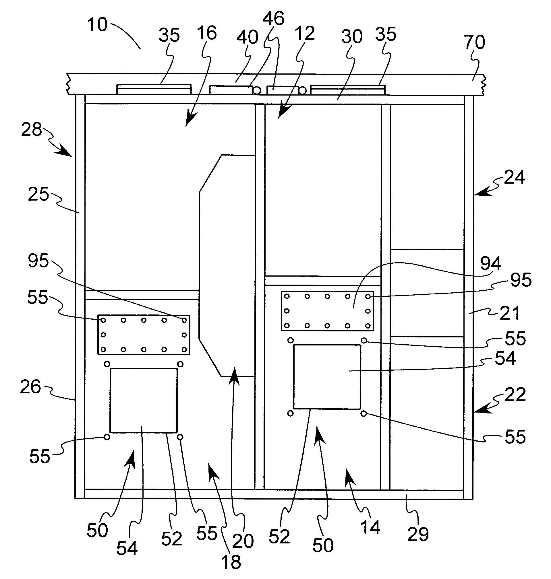
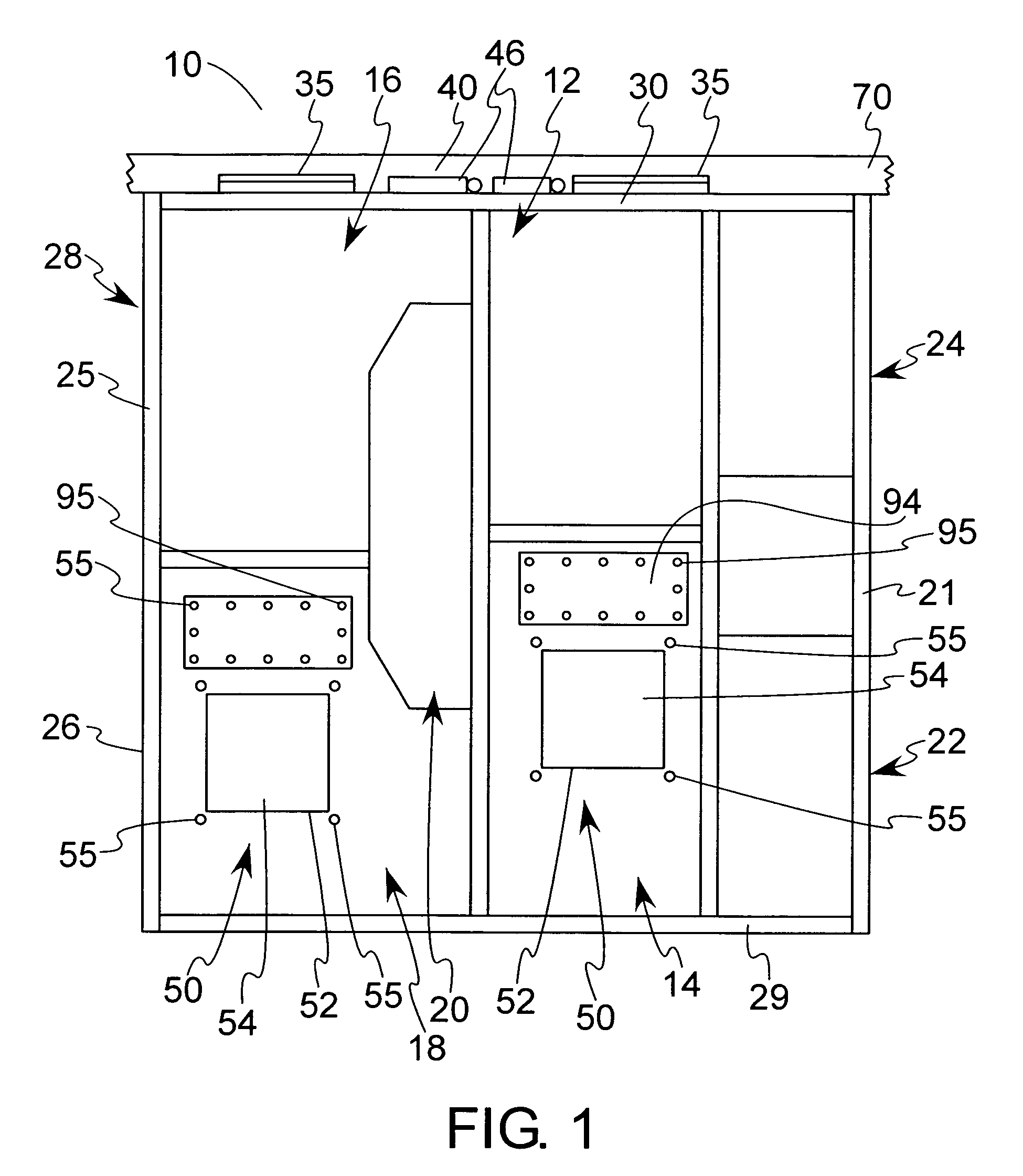
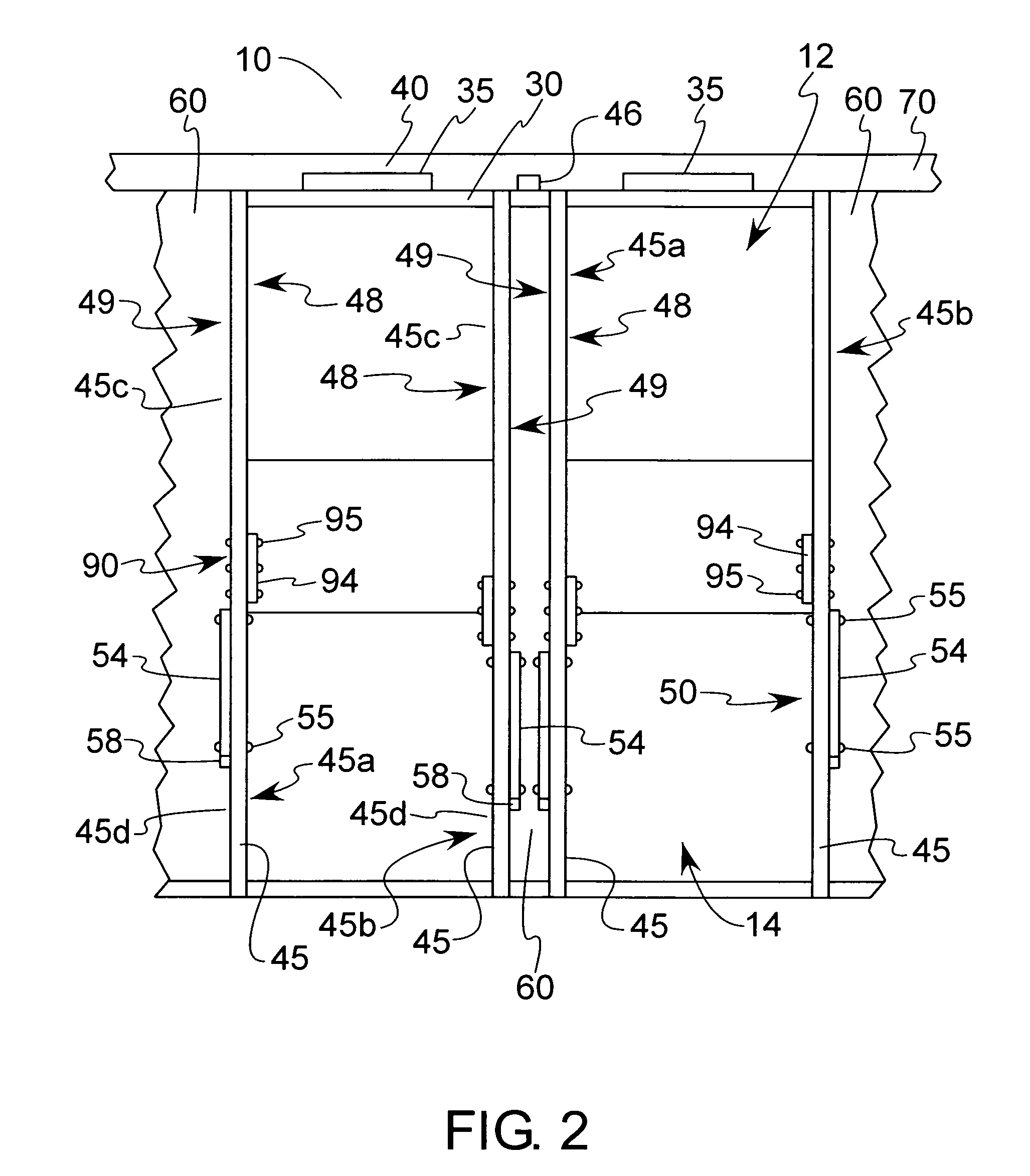
[0032]Having reference to the drawings, attention is directed first to FIG. 1 which discloses a vertical sectional view of an arc resistant switchgear assembly made in accordance with the present invention taken from the side of the assembly showing a schematic of the interior thereof designated generally by the numeral 10. As shown, it may be appreciated that the front of the assembly 10 is on the right. In comparing FIGS. 1 and 2, it will be appreciated that the arc resistant switchgear assembly 10 of this invention resembles some prior art switchgear assemblies in that it has a first front cubicle or breaker compartment 12, a second front cubicle or breaker compartment 14, a first rear cubicle or breaker compartment 16, a second rear cubicle or breaker compartment 18, and a main bus compartment 20. It is due to the fact that because so much of the breaker assembly of this invention incorporates structure already well known in the art, that fabrication and installation of this ass...


PUM


Abstract

An arc resistant switchgear assembly is provided having a front wall, a rear wall, a bottom surface, an upper surface, a first side wall, and a second side wall opposed to the first side wall and spaced a first distance from the first side wall, with each of the first and second side walls having an upper portion and a lower portion, and with each of the first and second side walls having an inner and an outer surface, with at least the lower portion of both the first side wall and the second side wall having at least one blow-off panel detachably secured thereto by fastening means. Each of the panels is detachably secured to the outer surface of the side wall to which each is secured. The assembly has a vertical plenum formed directly adjacent both the first and the second side walls, with the outer surface of each of the first and second side walls defining an inner side wall of each of the vertical plenums. The outer surface of the first side wall defines the inner side wall of one of the vertical plenums and the outer surface of the second side wall defines the inner side wall of an adjacent vertical plenum.

Description

BACKGROUND OF THE INVENTION[0001]1. Field of the Invention[0002]The present invention relates generally to electrical switchgear, and more particularly to arc resistant switchgear, and even more particularly to arc resistant switchgear that features dedicated vertical plenums.[0003]2. Description of the Related Art[0004]This invention is directed to the providing of arc resistant switchgear featuring a dedicated vertical plenum for each vertical switchgear cubicle. Arc resistant switchgear is electrical equipment designed to withstand the effects of an internal arcing fault. The occurrence of arcing inside electrical switchgear has many undesirable results. The arc energy can cause a sudden pressure increase inside the enclosure resulting in severe mechanical and thermal stress on the equipment, particularly the door.[0005]The arc itself can be caused by a bad breaker, the presence inside the switchgear of a small animal, bad insulation, or even lightning. As arcing begins, the gase...

Claims


Application Information

Patent Timeline
Patent Type & Authority Patents(United States)
IPC IPC(8): H05K7/20
CPCH02B13/025
Inventor DALIS, MANDELL
Owner PACS SWITCHGEAR LLC
Why Eureka
Try Eureka