Load handling platform provided with retractable rollers

a technology of a loading platform and a retractable roller, which is applied in the direction of rollers, conveyor parts, lifting devices, etc., can solve the problems of increasing the time required for loading and the mechanism is not adapted for use with the load handling device already in service, and achieves the effect of reducing the number of pieces, the cost of the unit, and the size of the uni

Active Publication Date: 2007-07-03
DIMECO
View PDF6 Cites 5 Cited by
  • Summary
  • Abstract
  • Description
  • Claims
  • Application Information

AI Technical Summary

Benefits of technology

[0007]The present invention proposes remedying these disadvantages with a roller device based on simple kinematics, reducing the number of pieces, the cost of the unit, and its size, which can be used either with new load handling devices or to retrofit existing ones.

Problems solved by technology

The mechanisms currently used in roller devices to ensure passage of the load from the “load support structure” to the “roller support structure” and vice versa present numerous drawbacks linked to their complexity, price, and space requirements.
Moreover, certain mechanisms require a broad amplitude of movement, increasing the time required for transferring the load.
Moreover, these mechanisms are not adapted for use with load handling devices already in service.

Method used


Image

  • Load handling platform provided with retractable rollers
  • Load handling platform provided with retractable rollers
  • Load handling platform provided with retractable rollers

Examples


Embodiment Construction

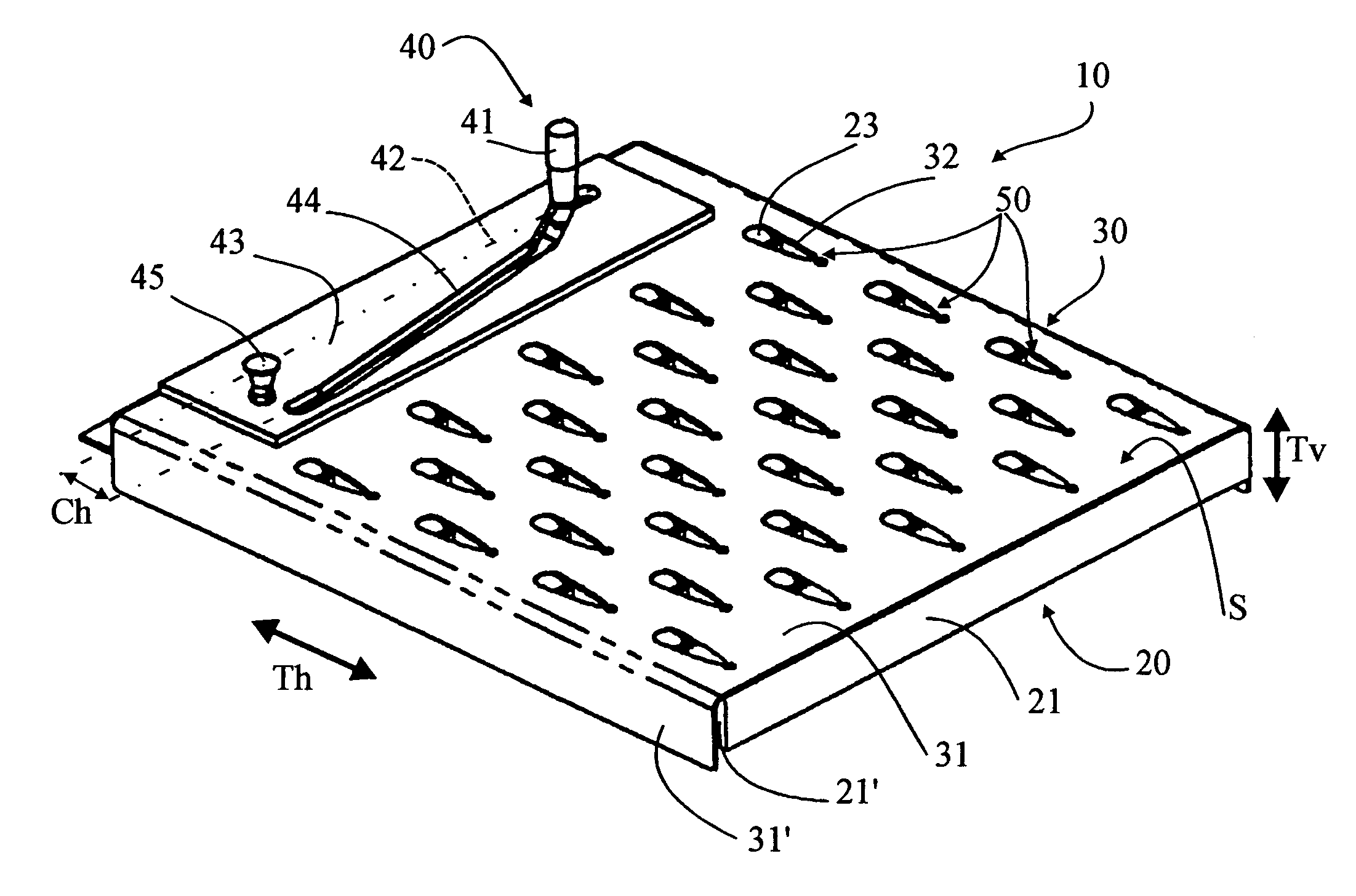
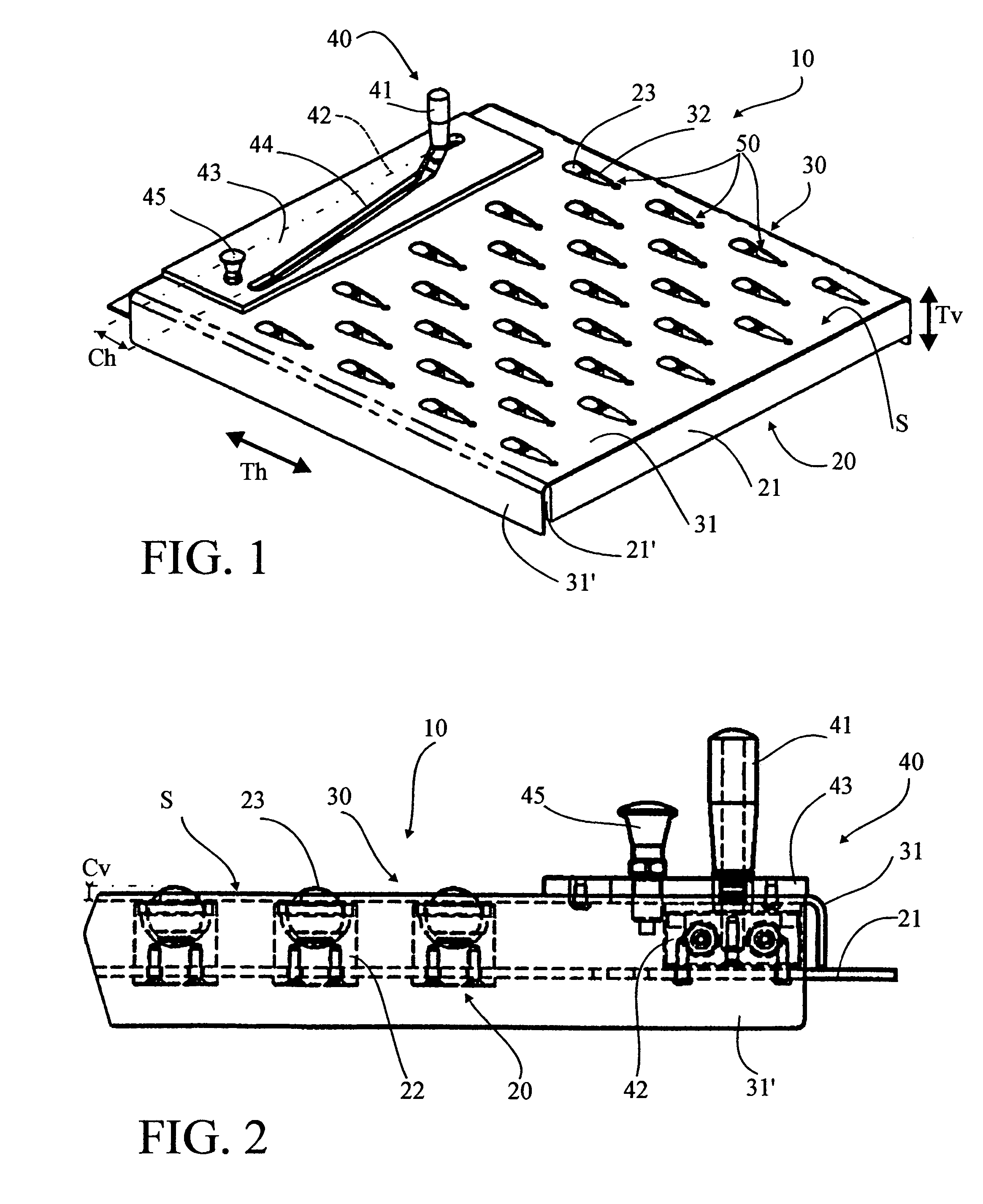
[0021]With reference to the drawings, roller device 10 according to the invention is formed like a platform and is designed to equip a conventional platform load handling apparatus (not shown). It ensures two functions: static maintenance with friction of heavy loads 1 weighing up to about two tons while the load handling device is moving, and dynamic maintenance of these loads 1 without friction while they are being transferred in a plane parallel to the platform. In certain applications, this roller device 10 can be used alone or in combination with other equipment.

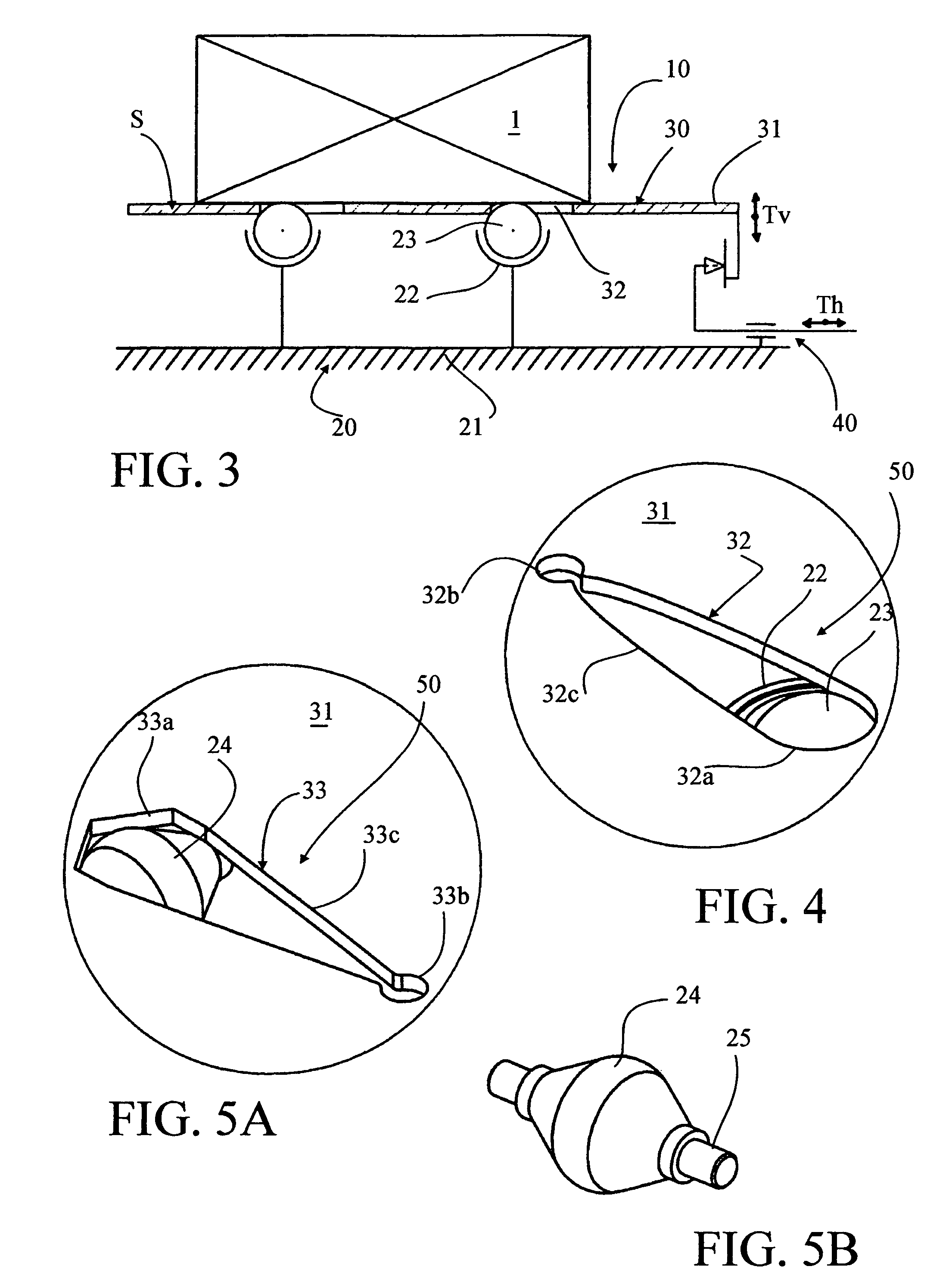
[0022]This roller device 10 comprises a roller supporting structure 20 consisting of roller elements 23 surmounted by a load supporting structure 30 having one plane contact surface S provided with openings 32 that allow at least the tops of roller elements 23 to be visible. In this exemplary embodiment, as shown schematically in FIG. 3, the load support structure 30 is movable relative to the fixed roller support struc...


PUM


Abstract

The invention concerns a roller track device based on simple kinematics, enabling reduction of the number of parts and production costs of the assembly as well as its space requirement, and designed for being fitted on new handling apparatuses as well as for retrofitting. The invention also concerns a platform or fork handling apparatus equipped with such a device. The roller track device (10) comprises a substantially horizontal table (21) whereon are mounted ball sockets (23), with a rack (31) mounted on top provided with openings (32) arranged opposite the balls (23). The rack (31) is mobile relative to the table (21) between a high position wherein it conceals the balls (23). A handle (41) coupled to the rack (31) enable its displacement in horizontal translation (Th). The openings (32) provided in the rack (31) consist of elliptical slots, which in combination with the spherical profiles of the underlying roller track device in the form of a platform with balls is also applicable to caster track platforms. The invention is useful for transferring heavy loads in a substantially horizontal plane with a platform handling apparatus for machine-tools, presses, injection machines and the like.

Description

[0001]This application is a national stage completion of PCT / FR2003 / 003126 filed Oct. 21, 2003 which claims priority from French Application Serial No. 02 / 13075 filed Oct. 21, 2002.FIELD OF THE INVENTION[0002]The present invention concerns a roller device for moving a load in an essentially horizontal plane and a handling apparatus equipped with such a roller device.[0003]In industry, load handling platforms such as elevator cars and stacking equipment, for example, are currently used to handle heavy loads. These heavy loads might consist of tools for machine tools or presses used to cut or stamp metal, or molds or forms used in the injection of synthetic material, etc. Generally, loads of less than two tons are transported on load handling platforms, while loads from two to ten tons are transported using fork apparatuses. Loads of over ten tons are transported by cranes.[0004]To facilitate the transfer of loads in the horizontal plane from the handling platform to the machine tool ...

Claims


Application Information

Patent Timeline
Patent Type & Authority Patents(United States)
IPC IPC(8): B65G13/12B60P1/52B65G39/02B66F9/12
CPCB60P1/52B65G13/12B65G39/025B66F9/12B66F9/195
Inventor MARCELLI, PIERRE
Owner DIMECO
Why Eureka
Try Eureka