Food metering and dispensing device

a technology for metering and dispensing devices, which is applied in the direction of liquid transferring devices, instruments, packaged goods, etc., can solve the problems of inapplicability of dispensers, frequent cleaning, and food products being transmitted, etc., and achieves convenient operation, simple structure, and convenient maintenance

Active Publication Date: 2007-07-03
QUANTUM TECHN SERVICES
View PDF9 Cites 29 Cited by
  • Summary
  • Abstract
  • Description
  • Claims
  • Application Information

AI Technical Summary

Benefits of technology

[0007]The difficulties encountered with previous dispensers has been overcome by the present invention. What is described here is a pump apparatus including a cylinder for containing a piston and for forming a product chamber, the cylinder having a longitudinal axis, an inlet and an outlet, a piston mounted in the cylinder, the piston having first, second and third apertures, a valve mounted in one of the piston apertures and having first, second and third lateral apertures and a connecting structure which allows both the piston and the valve to reciprocate together and allows the valve to move while the piston is stationary.
[0008]There are a number of advantages, features and objects achieved with the present invention which are believed not be available in earlier related devices. For example, several advantages are that the pump apparatus is a simply constructed, reliable, efficient and cost effective. Other features are that the pump apparatus is easy to operate, easy to maintain and easy to clean.

Problems solved by technology

A major problem with this dispenser is that the food product being transmitted includes chunks which clog the check valves and require frequent cleaning.
This procedure is very time consuming and thus the dispenser is not practical.

Method used


Image

  • Food metering and dispensing device
  • Food metering and dispensing device
  • Food metering and dispensing device

Examples


Embodiment Construction

[0034]While the present invention is open to various modifications and alternative constructions, the preferred embodiment illustrating the best mode contemplated by the inventor of carrying out his invention is shown in the various figures of the drawing and will be described herein in detail pursuant to Title 35 U.S.C. section 112 (first paragraph). It is understood, however, that there is no intention to limit the invention to the particular embodiment, form or example which is disclosed herein. To the contrary, the intention is to cover all modifications, equivalent structures and methods, and alternative constructions falling within the spirit and scope of the invention as expressed in the appended Claims section attached hereto, pursuant to Title 35 U.S.C. section 112 (second paragraph).

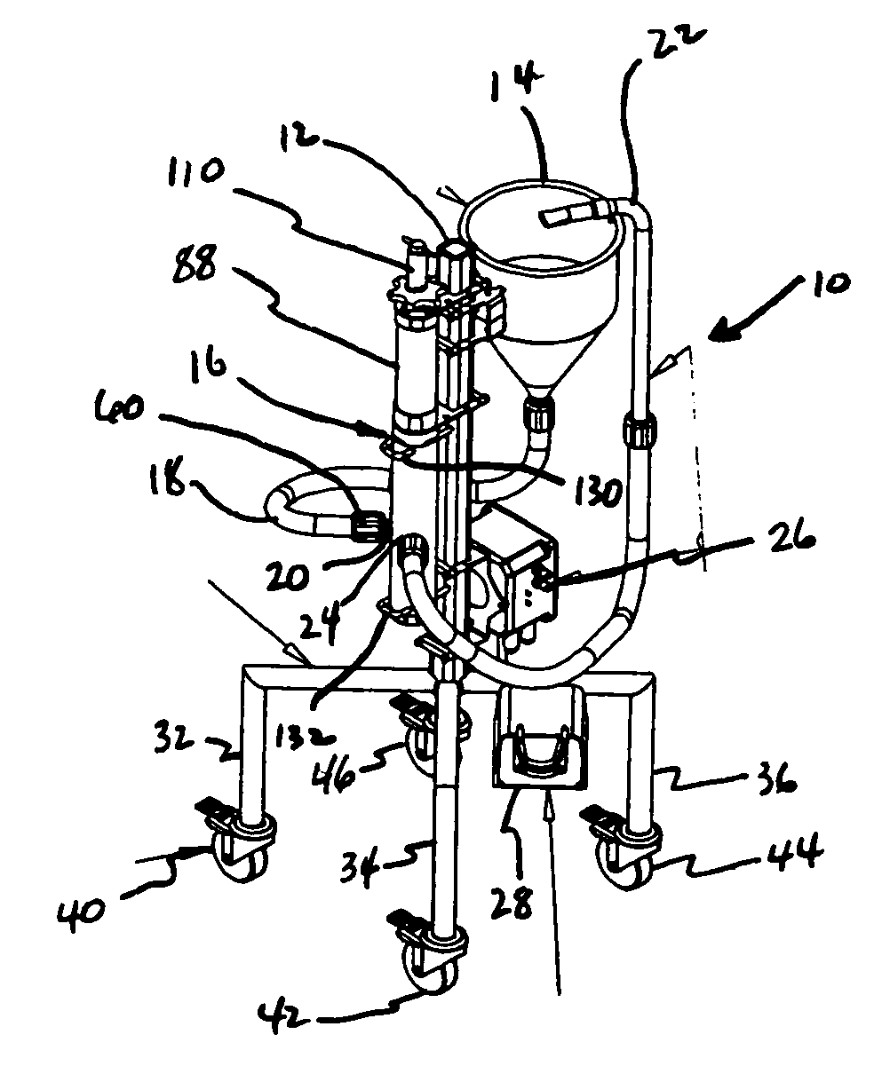
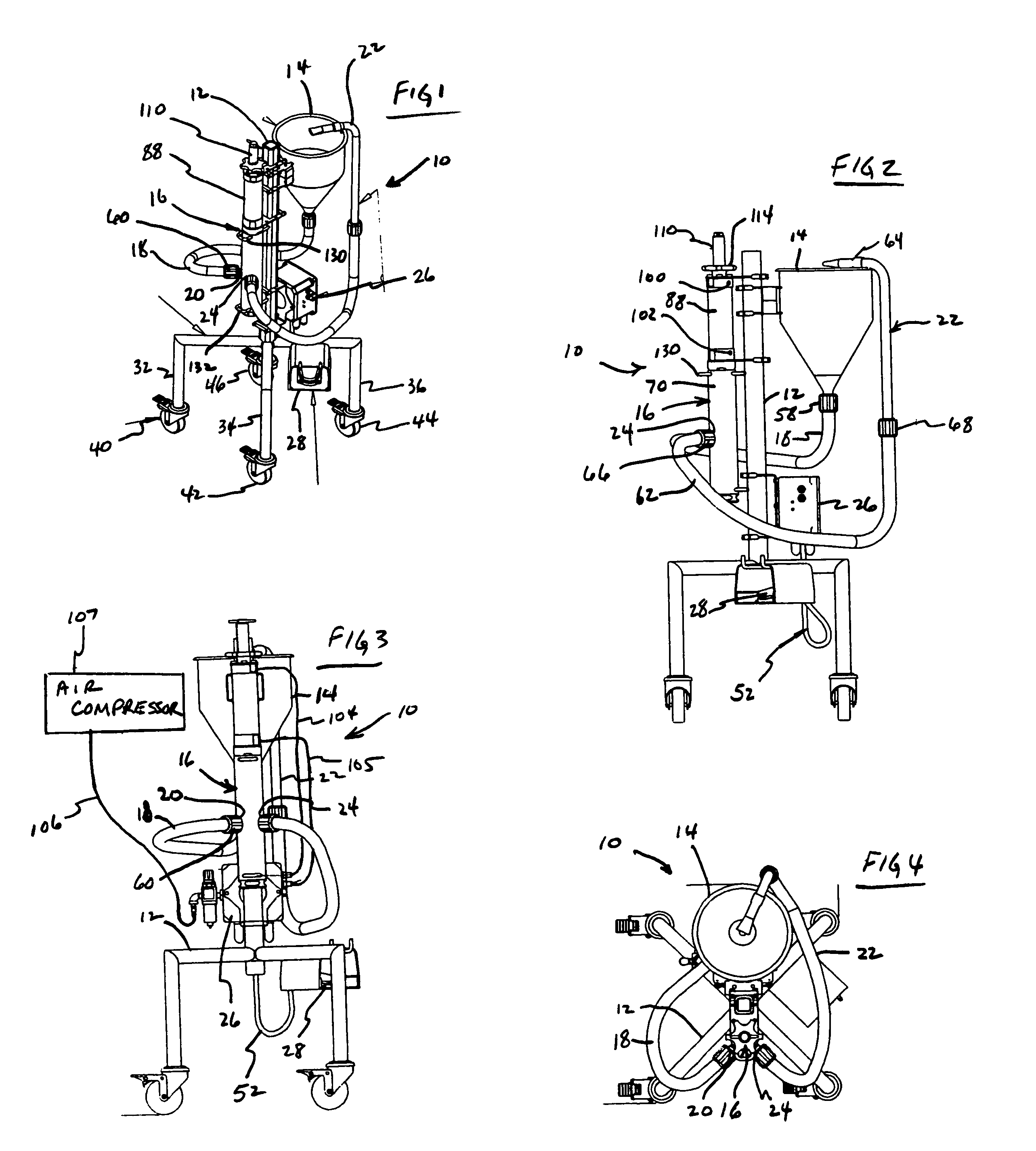
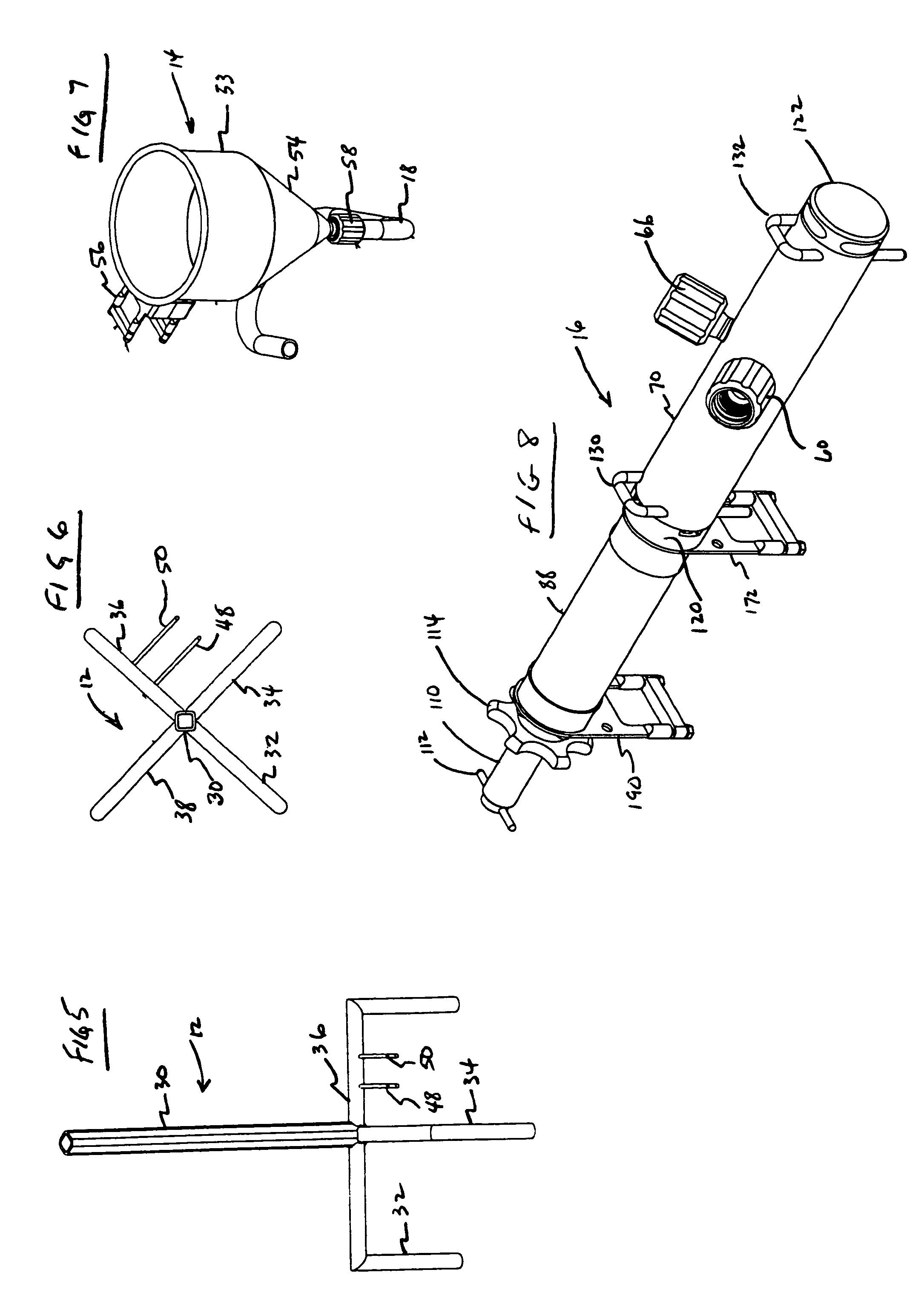
[0035]Referring now to FIGS. 1-4, there is illustrated a food metering and dispensing device 10 having a mounting frame 12, a food hopper 14 connected to the frame, an adjustable metering pump ...


PUM

PropertyMeasurementUnit
longitudinal distanceaaaaaaaaaa
volumeaaaaaaaaaa
timeaaaaaaaaaa

Abstract

A pump apparatus for an adjustable metering and dispensing pump apparatus for food products including a product piston moving in a product cylinder, the product cylinder being connected to a food hopper and a dispensing nozzle. The pump apparatus also includes a cylindrical valve moving within a central aperture in the product piston to selectively open and close passageways also in the product piston which communicate with intake and outlet ports connected to the product cylinder. The valve is attached to a valve piston moving within a valve piston cylinder and the valve piston cylinder is attached to a source of compressed air, to a sensor and to a control assembly. The control in turn is connected to a foot switch to allow an operator to initiate a cycle of the pump apparatus. The valve piston reciprocates both the valve piston and the product piston, however, while the valve moves directly with the valve piston, the product piston is connected with a lateral pin mounted in an elongated lateral slot formed in the product piston resulting in a delayed movement of the product piston. A screw is mounted to the valve piston cylinder to abut the valve piston in an adjustable manner so that the valve piston stroke is changeable resulting in a corresponding change in the volume of a food product in a product chamber in the product cylinder.

Description

CROSS REFERENCE TO RELATED APPLICATIONS[0001]Not applicable.STATEMENT REGARDING FEDERALLY SPONSORED RESEARCH[0002]Not applicable.BACKGROUND OF THE INVENTION[0003]1. Field of the Invention[0004]The present invention relates to a pump apparatus and more particularly to a pump apparatus having a valve within a piston for a metering and dispensing device that may be used for food products, the device being very efficient, reliable and simply constructed as well as easy to use and to wash.[0005]2. Description of the Related Art[0006]Dispensers for food products are known in the food industry. For example, a dispenser for barbecue sauce is constructed with a piston in a cylinder, an intake check valve and an outlet check valve. A major problem with this dispenser is that the food product being transmitted includes chunks which clog the check valves and require frequent cleaning. This procedure is very time consuming and thus the dispenser is not practical.BRIEF SUMMARY OF THE INVENTION[00...

Claims


Application Information

Patent Timeline
Patent Type & Authority Patents(United States)
IPC IPC(8): B67D5/42B67D7/60
CPCB65B3/326G01F11/023
Inventor FREUDINGER, MARK J.
Owner QUANTUM TECHN SERVICES
Why Eureka
Try Eureka