High speed metal drill bit

a metal drill bit, high-speed technology, applied in the direction of twist drills, manufacturing tools, wood boring tools, etc., can solve the problems of consuming excessive energy, not being productive and energy-efficient, affecting the drilling performance, etc., to maximize material removal, increase the drilling rate, and minimize energy consumption

Inactive Publication Date: 2007-07-03
UNIV OF MARYLAND +1
View PDF26 Cites 21 Cited by
  • Summary
  • Abstract
  • Description
  • Claims
  • Application Information

AI Technical Summary

Benefits of technology

[0008]The present invention provides the art with a drill bit capable of drilling a metallic material with an increased rate of drilling while minimizing energy consumption. The present invention provides a drill bit which maximizes the material removal into a cutting action while minimizing the energy consumption without any constraints from the helix angle. The present invention provides a suitable recess in the drill tip to maximize the flow of chips from the cutting edge to the outer helix of the shaft. The present invention provides an improved chip breaking which also improves removal efficiency. The present invention enables the rake face and the helix angles at their juncture to be independent of one another.

Problems solved by technology

Further, the process parameters, such as speed, bias load, and environmental condition affect the drilling performance.
Although conventional drill bits have good strength, they are not as productive and as energy efficient.
Further, current drill bits consume excessive energy.

Method used


Image

  • High speed metal drill bit
  • High speed metal drill bit
  • High speed metal drill bit

Examples


Embodiment Construction

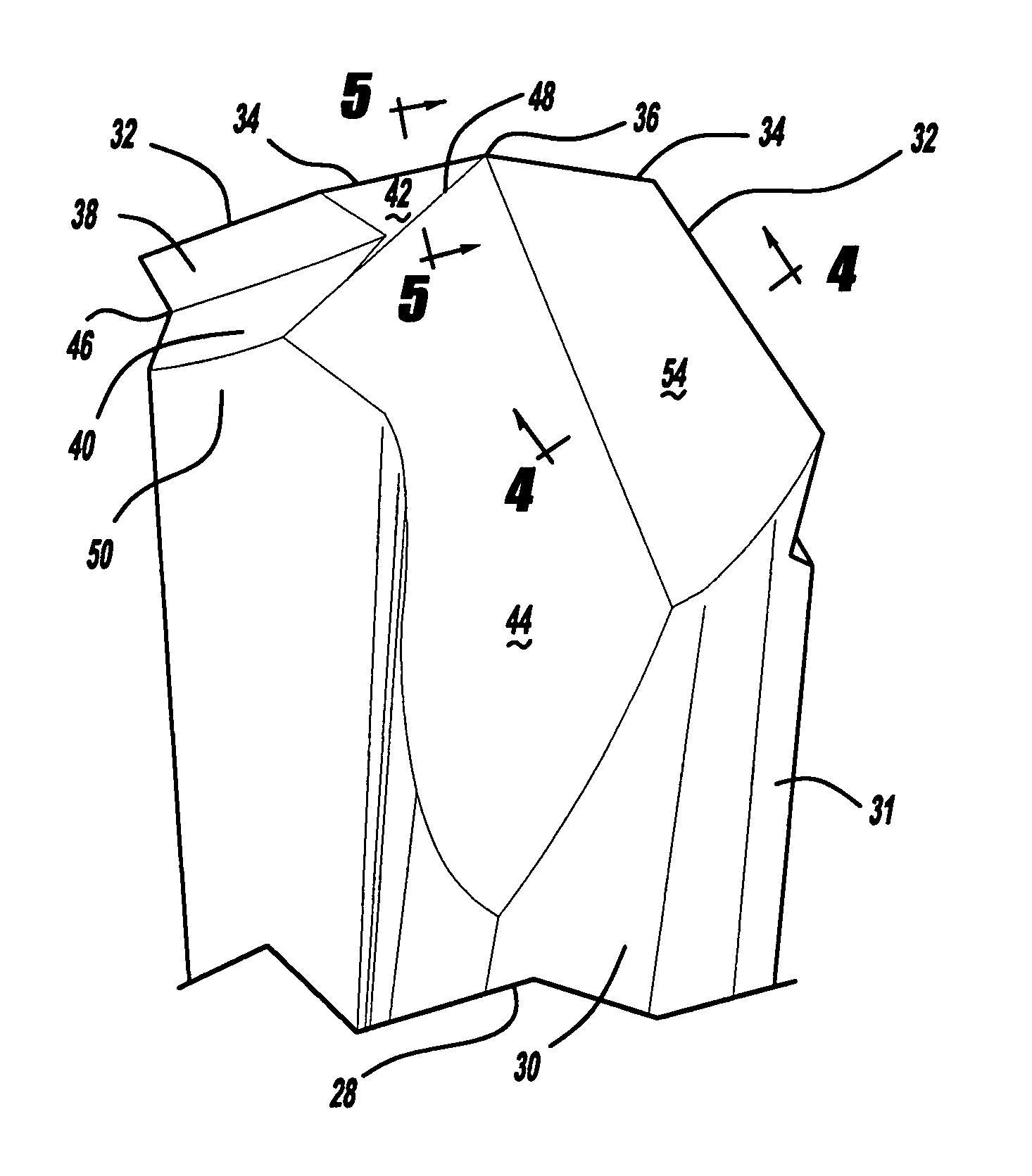
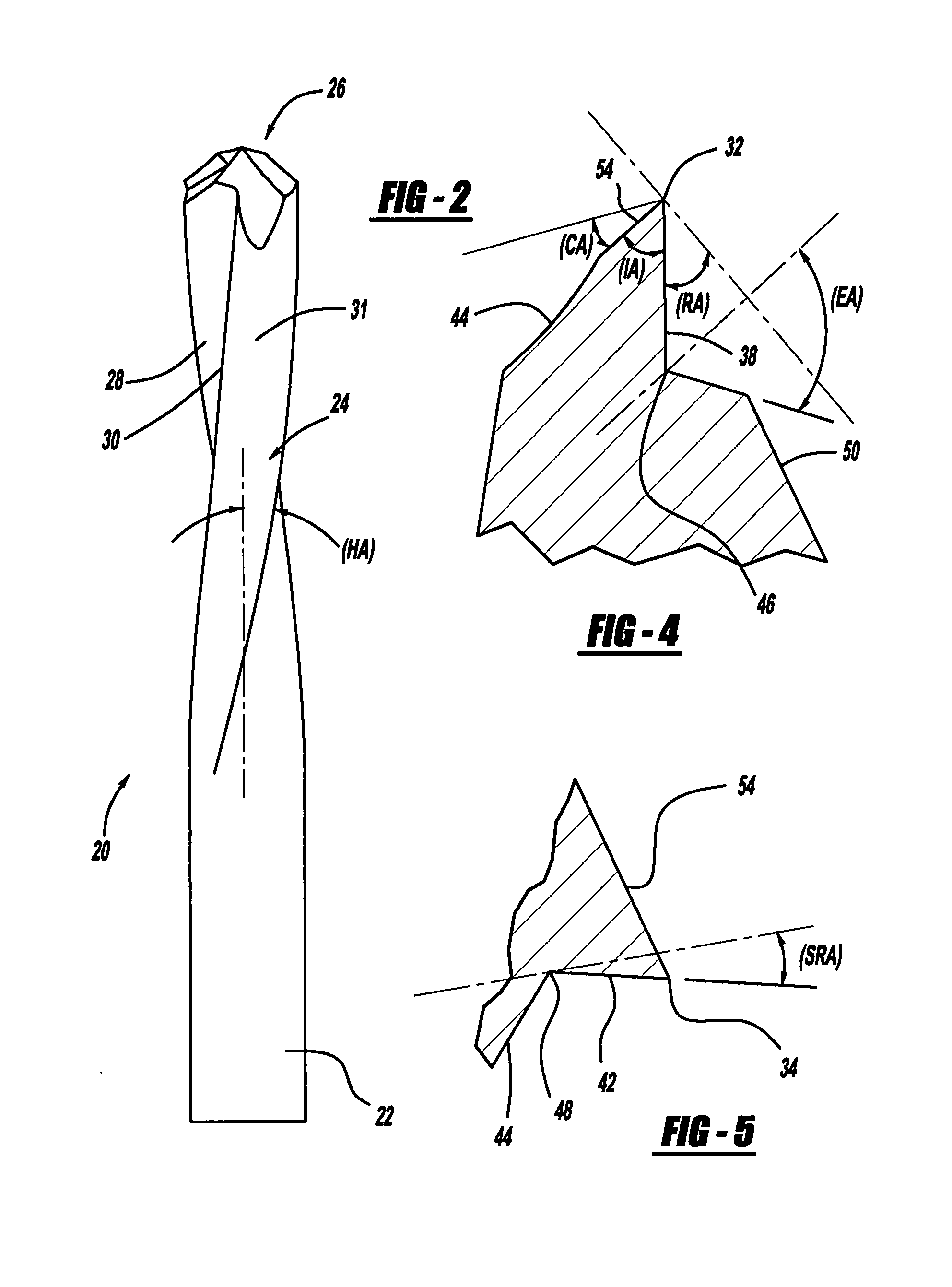
[0023]Turning to FIGS. 2 through 9a, a metal cutting drill bit in accordance with the invention is illustrated and designated with the reference numeral 20. The drill bit 20 includes a transmission portion 22 having a cylindrical or polygonal cross-section. A flute portion 24 is adjacent the transmission portion 22 and the flute portion 24 terminates at a tip 26. The flute portion 24 includes helical conveying grooves 28, as well as helical flutes 30. The helical flutes 30 have an outer surface 31 which defines the peripheral diameter of the drill bit 20.

[0024]The tip 26 includes a pair of primary cutting edges 32, a pair of secondary cutting edges 34 and a chisel tip 36. Each primary cutting edge 32 is defined by a primary rake face surface 38 and a primary clearance surface 54. The primary rake face is defined by a primary rake angle (RA) which can vary from 15° to 45°. Preferably, the rake angle (RA) is between 30° to 40° especially for a one-quarter inch diameter drill bit. The ...


PUM

PropertyMeasurementUnit
included angleaaaaaaaaaa
diameteraaaaaaaaaa
primary point angleaaaaaaaaaa

Abstract

A metal cutting drill bit has a shank portion, a flute portion defining a helix angle and a tip. The tip has a primary cutting edge extending to an outer periphery of the drill bit. The primary cutting edge has a rake face defining a rake angle. The rake angle is different from the helix angle at the tip of the drill bit.

Description

FIELD OF THE INVENTION[0001]The present invention relates to drill bits and, more particularly, to drill bits for drilling metallic material.[0002]A typical prior art bit is illustrated in FIGS. 1 and 1a and designated with the reference numeral 1. Functionally, the drill bit 1 consists of three components; a drive transmission shank end 2; a middle fluted body 3; and the drill tip 4. The drive transmission shank 2 is a solid rod of circular or polygonal cross-section that fits into a chuck or similar-mechanism of a portable drill. This arrangement enables the transmission of rotational torque and axial thrust force required to create a hole.[0003]The middle flute body 3 of the drill bit 1 has a double helix forming an outer helix around the solid core of the shaft. The outer helix provides a path to transport metal chips, generated by drilling, from the tip 4 of the drill bit 1 to the top plane of a hole. The flanks of the outer helix are tapered towards the shank to retain the chi...

Claims


Application Information

Patent Timeline
Patent Type & Authority Patents(United States)
IPC IPC(8): B23B51/02
CPCB23B51/02B23B2251/04Y10T408/909B23B2251/14Y10T408/9097B23B2251/043
Inventor ANJANAPPA, MUNISWAMAPPAXU, LICROSBY, STEPHEN R.RESCIGNO, GERALDTIMMONS, RUSSELL MTHOMAS, RICKEY J
Owner UNIV OF MARYLAND
Why Eureka
Try Eureka