Device for implanting occlusion spirals

a technology of occlusion spiral and stent, which is applied in the field of devices for implanting occlusion spirals, can solve the problems of tearing of the spiral within the blood vessel system, unsatisfactory bending stress or tensile strength, and the risk of a life-threatening embolism, and achieves the effect of ensuring the safety of the spiral, and ensuring the safety of the patien

a technology of occlusion spiral and stent, which is applied in the field of devices for implanting occlusion spirals, can solve the problems of tearing of the spiral within the blood vessel system, unsatisfactory bending stress or tensile strength, and the risk of a life-threatening embolism, and achieves the effect of ensuring the safety of the spiral, and ensuring the safety of the patien

US7238194B2Inactive Publication Date: 2007-07-03DENDRON

Image

  • Device for implanting occlusion spirals
  • Device for implanting occlusion spirals
  • Device for implanting occlusion spirals

Examples


Embodiment Construction

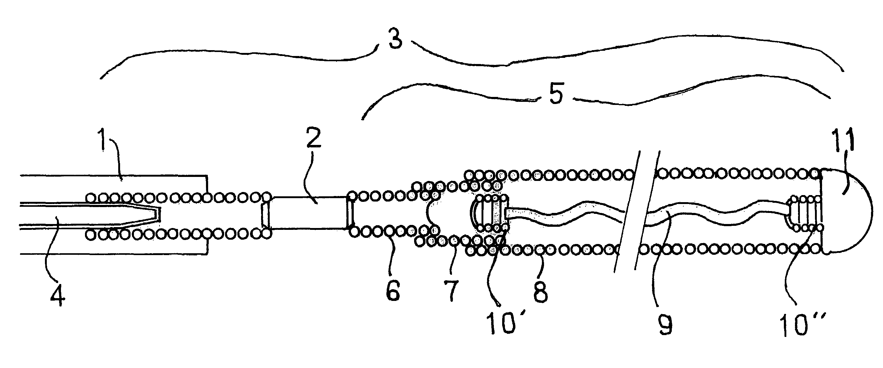
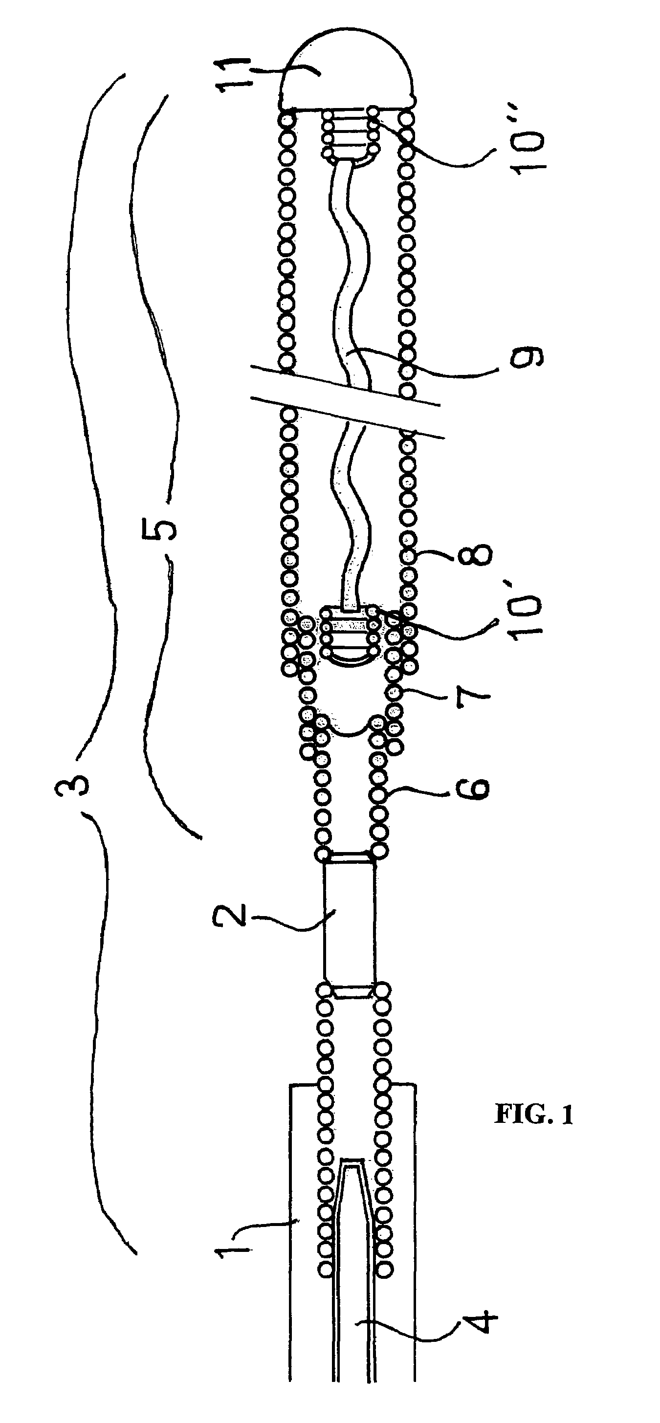
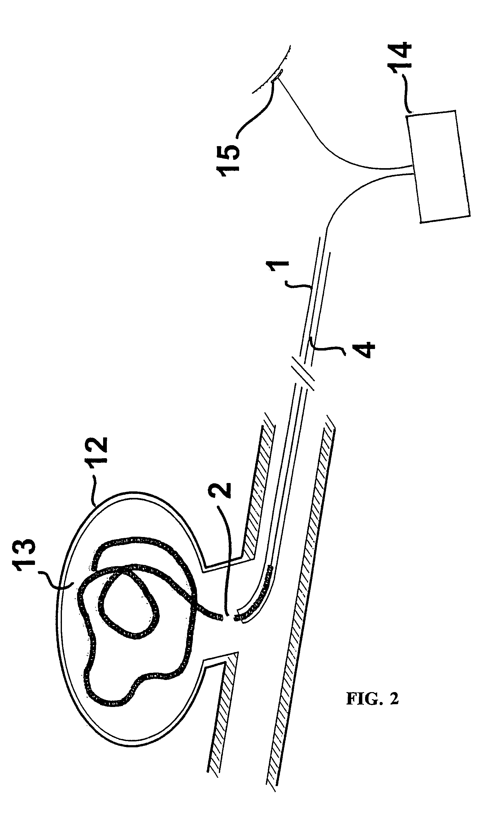
[0044]In FIG. 1, 1 refers to an electrically insulating catheter, particularly a flexibly structured microcatheter. An occlusion spiral 3 structured as a microspiral, made of a platinum / iridium alloy, provided with electrolytically corrodable locations 2 made of stainless steel, is pushed into the blood vessel system, out of the microcatheter 1, using the guide wire 4 that is attached to the occlusion spiral 3 using welding technology.

[0045]Since the connection between the guide wire 4 and the microspiral 3, which is produced by welding different materials, is not intended for electrolytic separation of the microspiral 3, it is structured to be particularly stable. The use of non-rusting stainless steel and a platinum alloy, respectively, for forming the guide wire, on the one hand, and the occlusion spiral, on the other hand, is particularly advantageous in this connection, since the nickel contained in the steel makes a very smooth and stable join with the platinum during welding....


PUM


Abstract

Device for implanting occlusion spirals in body cavities or blood vessels with a catheter, an occlusion spiral that can be moved within the catheter in the longitudinal direction, and at least one securing means attached in the occlusion spiral, structured as a flexible lengthwise element, which passes through the length of the occlusion spiral at least in a partial region, which is characterized in that the securing means contains a material with shape memory properties.

Description

BACKGROUND OF THE INVENTION [0001]The invention relates to a device for implanting occlusion spirals in body cavities or blood vessels with a catheter, an occlusion spiral that can be moved within the catheter in the longitudinal direction, and at least one securing means attached in the occlusion spiral, structured as a flexible lengthwise element, which passes through the length of the occlusion spiral at least in a partial region. The invention furthermore relates to an occlusion spiral as well as to a medical implant that is intended to be deposited in body cavities or blood vessels to be closed off.[0002]The use of endovascular techniques for the occlusion of body cavities or blood vessels such as arteries, veins, Fallopian tubes, or vascular malformations (e.g. vascular aneurysms) is a known state of the art. In this connection, the occlusion spiral is generally introduced and deposited in the cavity to be occluded using an endovascular guide wire, by means of a catheter.[0003...

Claims


Application Information

Patent Timeline
03 Jul 2007
Publication
US7238194B2
IPC
A61M29/00; A61B18/04; A61B17/12
CPC
A61B17/12022; A61B17/12113; A61B17/12145; A61B17/12154; A61B2017/12063
Inventors
MONSTADT, HERMANN; HENKES, HANS