Glazing element and laminate for use in the same

Inactive Publication Date: 2007-07-03
3M INNOVATIVE PROPERTIES CO
View PDF40 Cites 55 Cited by
  • Summary
  • Abstract
  • Description
  • Claims
  • Application Information

AI Technical Summary

Benefits of technology

[0028]The laminates of the invention have lamina comprised nonadhesive polymeric material that are “directly” adhered together by pressure sensitive adhesive, wi

Problems solved by technology

While such windows are typically tempered so that on impact they fracture in small irregular pieces without producing knife-like shards, they still provide a hazard to the occupants of a motor vehicle.
Such glass splinters could have a lacerative effect on the occupants of the motor vehicle and on any air bag that may have been inflated as a result of the automobile accident.
However, when laminated sidelights are broken, they typically leave sharp glass shards attached to the PVB interlayer which can cause severe laceration to the occupants of the vehicle.
The impact fracture problem also exists in the case of architectural glazing where tempered or annealed glass panels are employed for windows and doorways.
Impact fracturing of such glass panels may cause spall which would be a hazard to anyone in the immediate vicinity of the fractured panel.
While there is a multitude of patents disclosing various combinations

Method used


Image

  • Glazing element and laminate for use in the same
  • Glazing element and laminate for use in the same

Examples


example 1

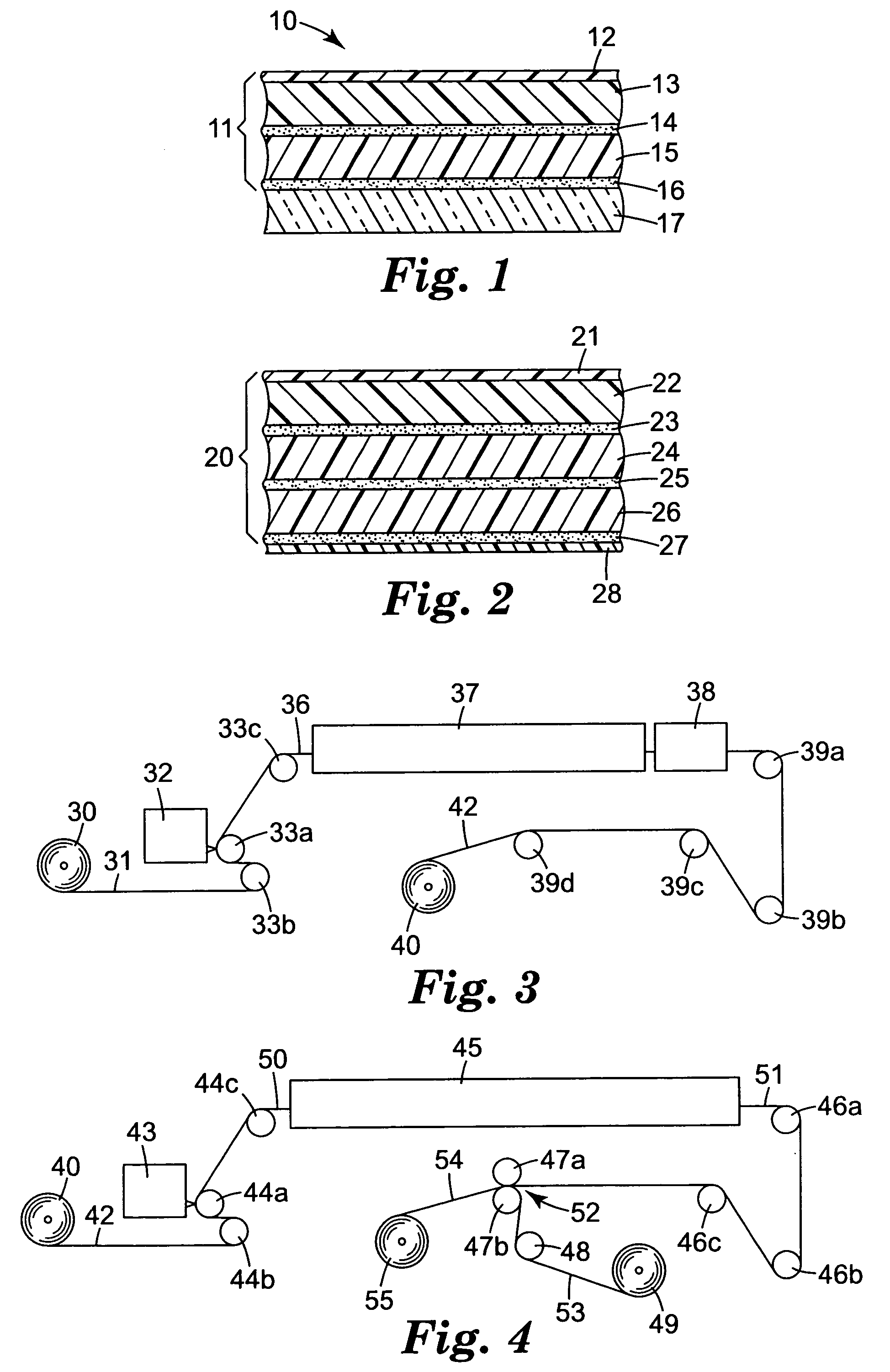
[0080]The Hardcoat Coating Composition described above was further diluted with isopropyl alcohol to obtain a 21% solids solution to which was added 0.1% by weight of a smoothing agent (Dow™ 57). The resultant coating composition was coated by use of equipment shown in FIG. 3, with an extrusion die. The coating was applied to a polyester film (Melinex™ 454-200) to obtain, after drying and curing, a dry coating weight of 0.3 gram per square foot (3.2 grams per square meter).

[0081]The coating conditions for the equipment shown in FIG. 3 were as follows:[0082]Extrusion die3 opening: 4 mil (0.38 mm)[0083]Film speed: 55 feet per minute (16.8 meters per minute)[0084]Film tension: 1 lb / inch (0.18 kg per cm)[0085]Oven zone temperatures: (1): 110° F. (43° C.); (2): 120° F. (49° C.); (3): 120° F. (49° C.)[0086]Oven zone length: 40 feet (12.2 meters)[0087]Coating width: 52 inches (1.32 meter)[0088]UV light source: high pressure mercury bulb with parabolic reflectors—67 kw total output

[0089]Two...

example 2

[0093]Example 2, which is a comparative example, was prepared in the same manner as Example 1, with the exception being that the pressure sensitive adhesive was obtained from Adhesive D Solution to show the effect of using a stiffer pressure sensitive adhesive.

example 3

[0094]Example 3 was made according to the present invention. One uncoated Melinex™ 454-400 4 mil thick film (0.1 mm) and one uncoated Melinex TM 454-300 3 mil film (0.076 mm) were laminated together by use of the equipment depicted in FIG. 4. The first of the films was coated with Adhesive C Solution described above using a notch bar coater having a coating gap between the bar and the film of 4 mils (0.102 mm) to provide a dry adhesive coating of 0.45 mil (0.011 mm). The film speed was 10 feet (3.05 meters) per minute under a tension of about 1 lb per inch (0.18 kg per cm). The oven had three 12 foot (3.7 meter) heated zones, heated as follows: (1) 120° F. (49° C.); (2) 180° F. (82° C.); and (3) 200° F. (93° C.). The second film was laminated to the adhesive coated side of the first film at nip rolls 47a and 47b depicted in FIG. 4. Nip roll 47a was a 16 inch (41 cm) diameter steel roll heated at 160° F. and roll 47b was an 18 inch (46 cm) diameter rubber roll having a Shore A durome...


PUM

PropertyMeasurementUnit
Temperatureaaaaaaaaaa
Lengthaaaaaaaaaa
Lengthaaaaaaaaaa

Abstract

A multi-layer optically clear laminate suited for attachment to window glass to provide a glazing element which has reduced spall and lacerative consequences on fracture impact of the window glass is provided by the invention. The laminate is comprised of at least two films of nonadhesive polymeric material directly adhered together by pressure sensitive adhesive and includes an exposed surface covered with a hard coat composition and an opposite surface covered with an ambient temperature attachable pressure sensitive adhesive. A glazing element comprised of the laminate attached to glass is also provided.

Description

BACKGROUND OF THE INVENTION[0001]1. Field of the Invention[0002]This invention relates to a multi-layer optically clear laminate suited for attachment to window glass to provide a glazing element which has reduced spall and lacerative consequences on impact fracture of the window glass and to glazing elements made with the same.[0003]2. Description of Related Art[0004]The invention of laminated glass windshields for use in motor vehicles has substantially reduced injuries caused by occupant-windshield impacts resulting from automobile accidents. Such laminated windshields are made by laminating under heat and pressure two glass plates with an interlayer of a tough, transparent, extensible, material such as polyvinyl butyral (PVB). While such a laminated windshield provides some degree of protection for motor vehicle occupants, it is still generally conventional to utilize unlaminated glazing elements for fabricating the other windows of automobiles. While such windows are typically ...

Claims


Application Information

Patent Timeline
IPC IPC(8): B32B33/00B32B17/10B60J1/00B32B27/00C03C17/32C03C17/34
CPCB32B17/10009B32B17/1033B32B17/10779C03C17/3405C03C17/324B32B2367/00Y10T428/28Y10T428/1471Y10T428/1452Y10T428/14Y10T428/31786B32B27/36
Inventor DIETZ, PETER T.
Owner 3M INNOVATIVE PROPERTIES CO
Why Eureka
Try Eureka