Multi-component conductive polymer structures and a method for producing same

a polymer structure and multi-component technology, applied in the direction of non-metal conductors, conductors, synthetic resin layered products, etc., can solve the problems of difficult extrusion and draw into fibers of traditional conductive fillers such as carbon black, metal or metal oxide powders, and significantly lower electrical conductivity in those regions

Inactive Publication Date: 2007-07-03
CATALYTIC MATERIALS
View PDF20 Cites 71 Cited by
  • Summary
  • Abstract
  • Description
  • Claims
  • Application Information

AI Technical Summary

Problems solved by technology

Thermoplastics such as nylon and polyester that contain traditional particulate conductive fillers such as carbon black, metal or metal oxide powders are difficult to extrude and draw into a fiber.
Such a material, however, suffers from the fact that while the bulk properties of the polymer exhibit high electrical conductivity, the poor contact of the conductive component with the exposed polymer surface results in a significantly lower electrical conductivity in those regions.

Method used


Image

  • Multi-component conductive polymer structures and a method for producing same
  • Multi-component conductive polymer structures and a method for producing same
  • Multi-component conductive polymer structures and a method for producing same

Examples


example 1

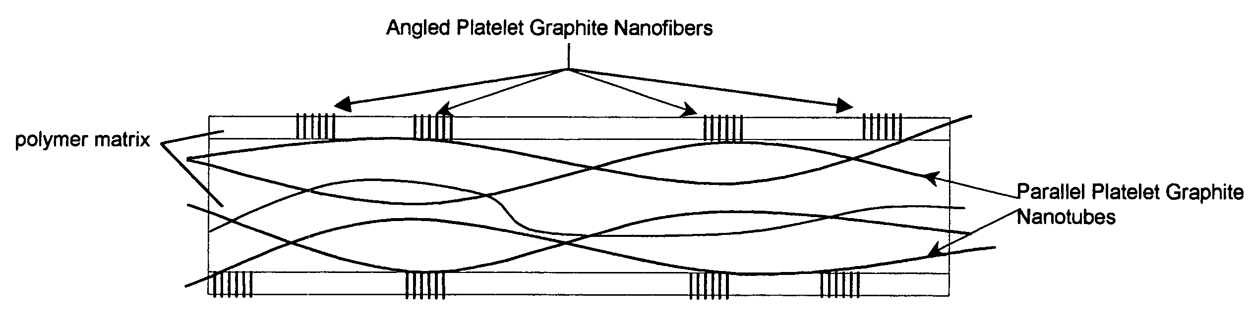
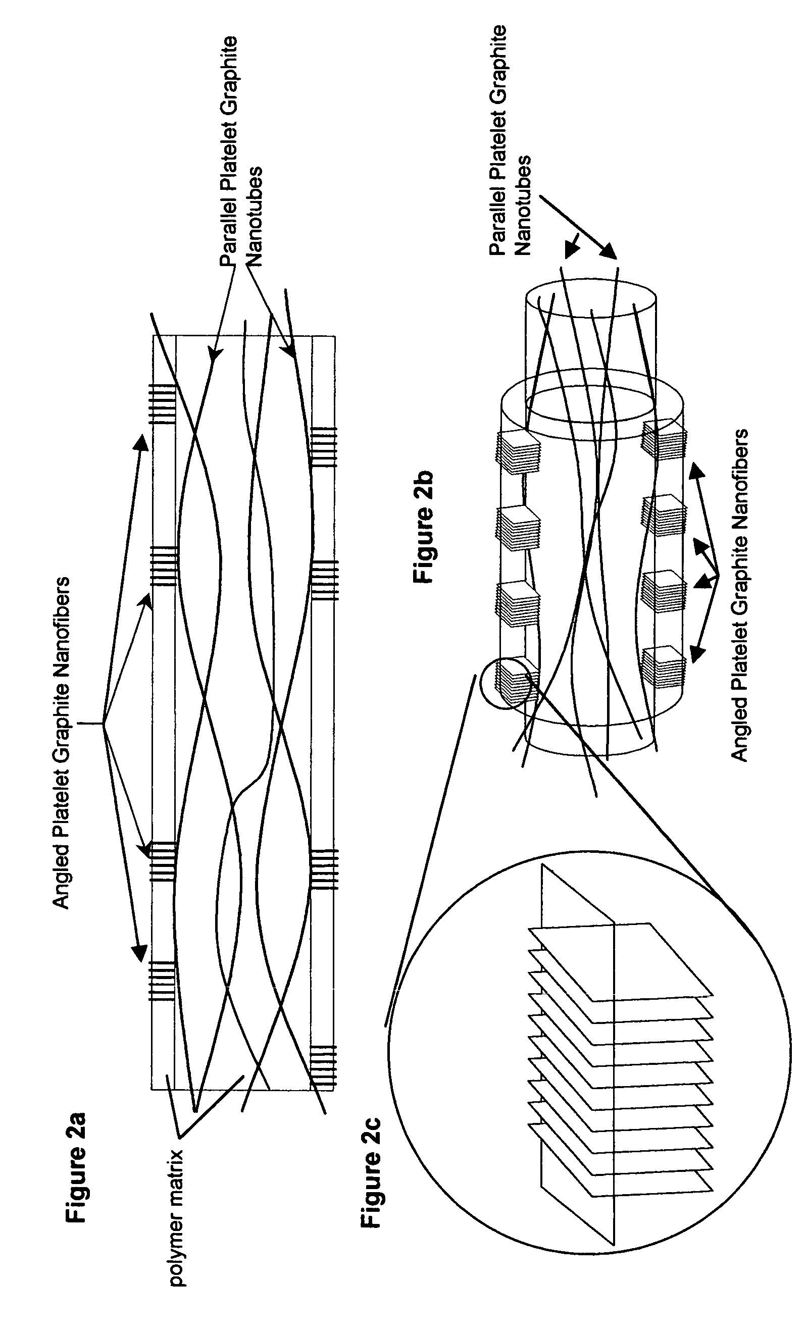
[0038]About 5.0 wt. % of multi-faceted graphitic nanotubes were incorporated into a polycarbonate. The bulk resistivity of the polycarbonate containing multi-faceted nanotubes will be found to be about 105 Ω. cm and a corresponding surface resistivity will be found to be about 104 Ω. cm2. If this sheet of polymcarbonate containing graphitic nanotubes is covered with a second sheet of polycarbonate, but instead containing about 5 wt. % of either “platelet” or “herring-bone” graphite nanofibers the surface resistivity of this combination to found to reach a value of about 103 Ω. cm2. That is, the surface conductivity will be found to be enhanced by a factor of 10.

example 2

[0039]The combination of the hollow tubular structure of the multi-walled multi-faceted carbon nanotube and the “platelet” graphite nanofiber structure offers high electrically conductivity and exclusive gas transport channels, since the internal diameter of the former materials is about 3 nm and for the most part inaccessible to liquids. The utilization of carbon nanostructures in the Gas Diffusion Layer results in a surface that has a significantly lower degree of roughness than that of the currently used materials. As a consequence, when a newly fabricated Gas Diffusion Layer is brought into contact with a membrane perforations or leaks will be substantially reduced.

example 3

[0040]In a series of experiments, various types of carbons were dispersed in aqueous solution and blended with a polyethylene terephthalate (PET) resin to produce conductive inks. The data presented in Table 1 shows the wt. % (of the resin) carbon filler loading and the corresponding electrical resistivities of the inks. Examination of the results clearly demonstrates that the ink containing the bi-component filler exhibits the highest electrical conductivity.

[0041]

TABLE 1Electrical Resistivity of Various Conductive InksResistivityFillerWt. % carbonohm · cmCarbon Black1.0 1 × 10¹²Multi-faceted Nanotube1.02 × 106Multi-faceted graphite nanotube +1.01 × 10⁵platelet graphite nanofiber(4:1)


PUM

PropertyMeasurementUnit
angleaaaaaaaaaa
aspect ratioaaaaaaaaaa
angleaaaaaaaaaa

Abstract

Novel electrically conductive polymer composite structures having a horizontal plane that contain effective amounts of two different types of conductive graphitic nanofibers. The first type of graphitic nanofiber is aligned substantially parallel to the horizontal plane of the polymer structure and are comprised of graphite platelets that are aligned substantially parallel to the longitudinal axis of the nanofiber. The second type of conductive graphite nanofiber are aligned at an angle to the horizontal plane of the polymer structure and are comprised of graphite platelets aligned at an angle to the longitudinal axis of the nanofiber. The conductive polymer composite structures are further comprised of one or more polymer layers.

Description

FIELD OF THE INVENTION[0001]This invention relates to novel electrically conductive polymer composite structures having a horizontal plane that contain effective amounts of two different types of conductive graphitic nanofibers. The first type of graphitic nanofiber is comprised of graphite platelets that are aligned substantially parallel to the longitudinal axis of the nanofiber. The second type of conductive graphite nanofiber that is comprised of graphite platelets that are aligned at an angle to the longitudinal axis of the nanofiber. Further, a fraction of the graphite platelets constituting the latter nanofibers protrude from the polymer surface, thus allowing electrons to flow to these exposed regions. The conductive polymer composite structures are further comprised of one or more polymer layers.BACKGROUND OF THE INVENTION[0002]It is well established that the incorporation of certain types of carbon nanofibers into polymeric materials can impart electrical conductivity to s...

Claims


Application Information

Patent Timeline
Patent Type & Authority Patents(United States)
IPC IPC(8): B32B27/12H01B1/00
CPCB82Y30/00D01F1/09D01F8/06D04H1/42Y10T428/2931Y10S977/70Y10S977/778Y10T428/2929D04H1/4242Y10T428/249924Y10T428/24994Y10T428/24995D04H1/43828D04H1/43832D04H1/43838
Inventor RODRIGUEZ, NELLY M.BAKER, R. TERRY K.
Owner CATALYTIC MATERIALS
Why Eureka
Try Eureka