
Two-dimensional ionising particle detector

a detector and ionising particle technology, applied in the direction of instruments, x/gamma/cosmic radiation measurement, radiation particle tracking, etc., can solve the problems of image limit the final resolution of the source, imperfections in the regular arrangement of pixels, and the inability to guarantee the colinearity between each fibr

Inactive Publication Date: 2007-07-03
COMMISSARIAT A LENERGIE ATOMIQUE ET AUX ENERGIES ALTERNATIVES
View PDF9 Cites 39 Cited by
  • Summary
  • Abstract
  • Description
  • Claims
  • Application Information

AI Technical Summary

Benefits of technology

The invention is a two-dimensional ionising particle detector that uses a matrix of detecting fibres to capture images with high resolution. The detector is made up of glass capillaries filled with a liquid scintillator, which allows for the detection of fast neutrons and gamma rays. The refraction index of the glass is chosen so that the average free path of the primary scintillation photons is negligible compared with the diameter of the capillary. This design improves the detection of particles with high energy levels and allows for better spatial resolution. The detector can be made with a high degree of stiffness and precision colinearity between the detecting fibres. The invention also addresses limitations in previous two-dimensional detectors, such as the need for high-speed imaging and the difficulty in achieving high resolution.

Problems solved by technology

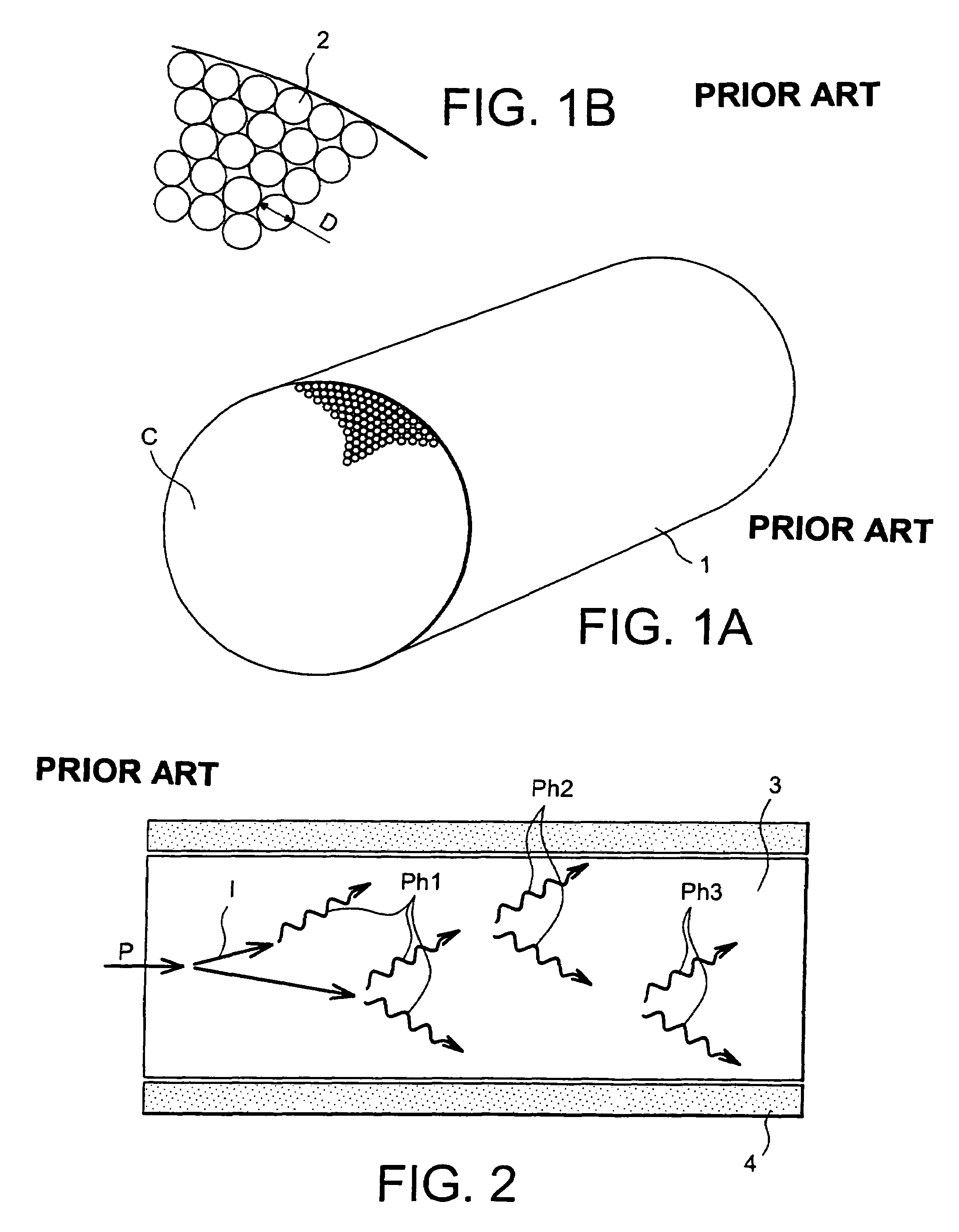
It is also known that sampling an image limits the final resolution in the source to twice the size of a pixel divided by magnification of the imagery system.
Moreover, a detector is made by the painstaking assembly of several thousand pixels one by one.
The result is imperfections in the regular arrangement of pixels.
Furthermore, the lack of stiffness of plastic scintillator fibres and their high expansion makes it impossible to guarantee precise colinearity between each fibre.
Therefore another limitation of the spatial resolution in the source is the width of energy deposition (cylinder diameter) divided by the magnification.
Thus, the technology for manufacturing two-dimensional detectors according to known art limits the performances of the instruments in which these detectors are located.

Method used


Image

  • Two-dimensional ionising particle detector
  • Two-dimensional ionising particle detector
  • Two-dimensional ionising particle detector

Examples


Embodiment Construction

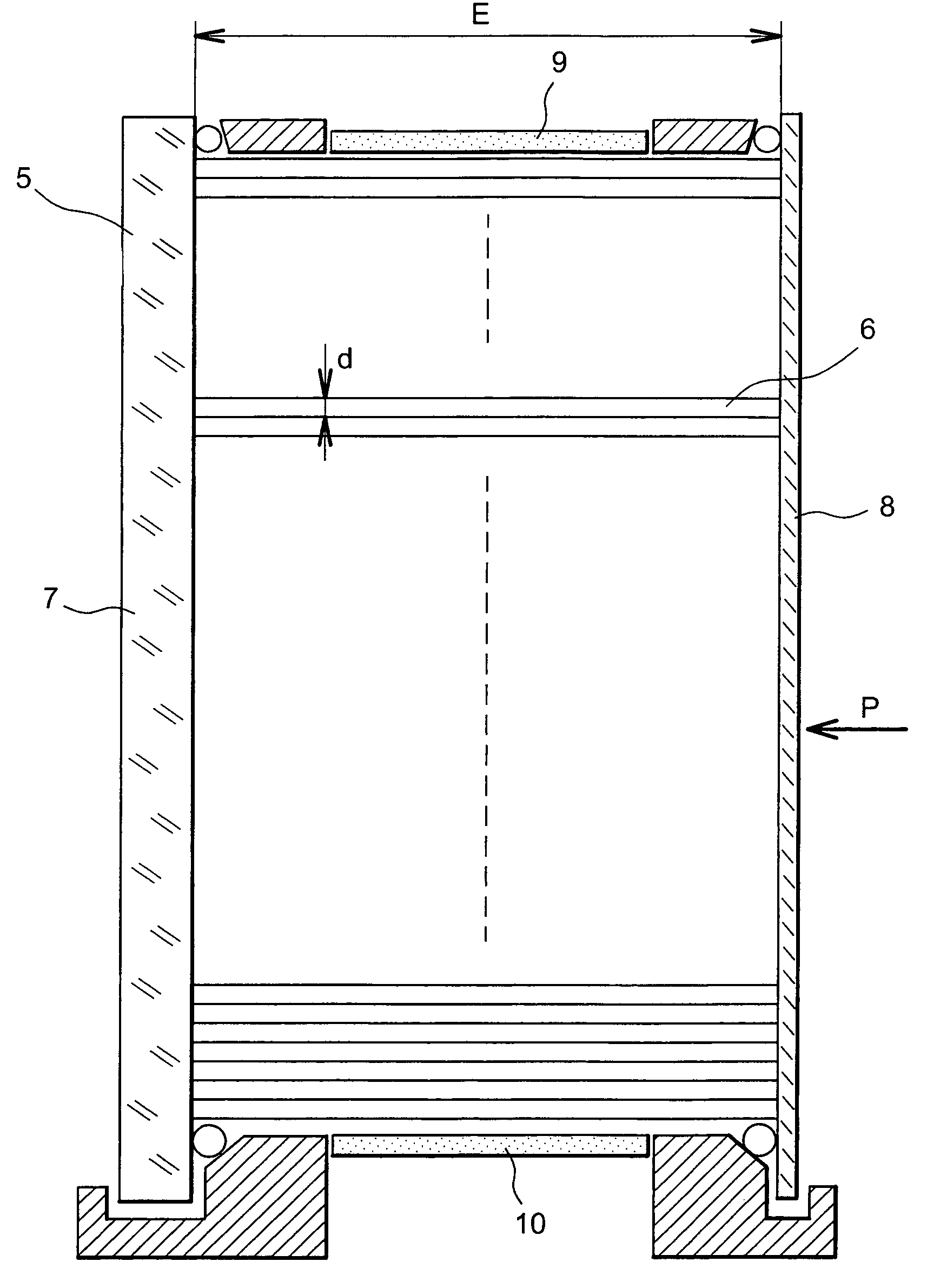
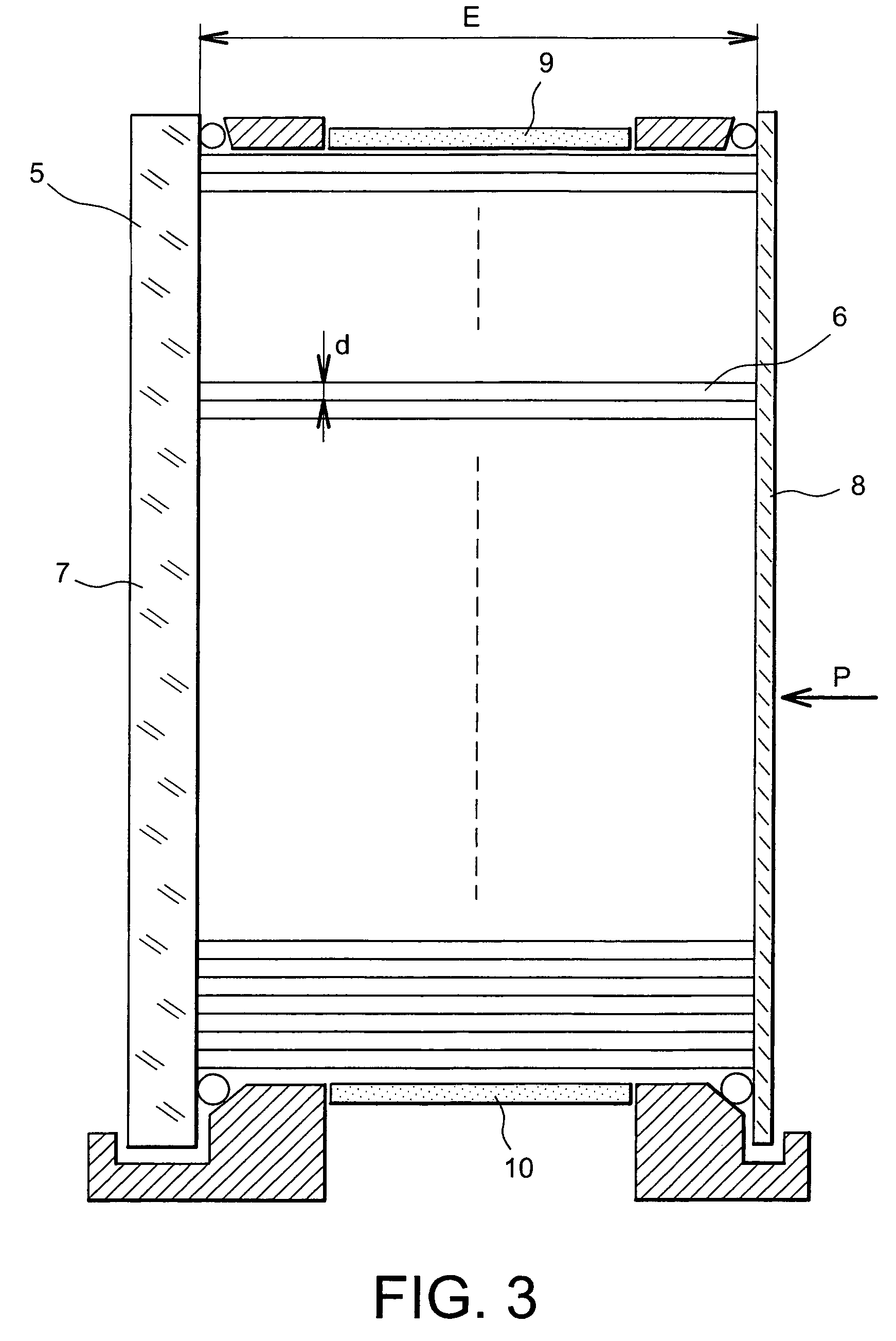
[0020]FIG. 3 shows a two-dimensional ionising particle detector according to the invention.

[0021]The two-dimensional detector according to the invention comprises a capillary matrix 6 filled with a liquid scintillator. The capillary matrix 6 is placed in a vat 5. For example, the capillaries have an average diameter d less than or equal to 500 μm and can be as small as 20 μm. The refraction index of glass in the capillaries may for example be 1.49. The parallelism of capillaries is less than 100 micro-radians. The path of incident particles is parallel to the centre line of the capillaries.

[0022]For example, the liquid scintillator has a refraction index of 1.57. The chemical composition of the liquid scintillator is chosen such that the average free path of primary scintillation photons is negligible compared with the diameter of the capillary. For example, the wavelength of primary scintillation photons induced in the solvent will be 300 nm.

[0023]The liquid scintillator is either ...


PUM


Abstract

A two-dimensional ionising particle detector including a matrix of detecting fibers, each detecting fiber forming a pixel of the detector. Each detecting fiber is composed of a glass capillary filled with a liquid scintillator for which the chemical composition is chosen such that an average free path of primary scintillation photons is negligible compared with a diameter of the capillary. The detector is applicable, for example, to high resolution particle imagery.

Description

TECHNICAL DOMAIN AND PRIOR ART[0001]The invention relates to a two-dimensional ionising particle detector.[0002]For example, the invention is applicable to the domain of particle imagery with a high penetration capacity.[0003]Particle imagery with a high penetration capacity (for example fast neutrons or gamma rays) requires detectors with a good resolution and a high stopping power.[0004]For example, this type of detector is used for the fusion of deuterium (DD) or a mix of deuterium (D) and tritium (T) by inertial confinement using a power laser. Fusion of these hydrogen isotopes takes place in a volume with a 50 μm characteristic dimension. The fusion nuclear reaction is accompanied by release of a 14.1 MeV fast neutron for a DT mix or a 2.45 MeV fast neutron for a DD mix. Fast neutrons have sufficiently long free path to come out of the fuel. The neutronic image localises the area in which hydrogen isotopes burn. The neutronic image or the gamma image is formed either by a pinho...

Claims


Application Information

Patent Timeline
Patent Type & Authority Patents(United States)
IPC IPC(8): G01T3/06G01T1/20G01T1/00G01T1/204G01T5/08
CPCG01T1/201G01T1/204
Inventor DISDIER, LAURENTFEDOTOFF, ALEXANDRE
Owner COMMISSARIAT A LENERGIE ATOMIQUE ET AUX ENERGIES ALTERNATIVES
Learn More