Electrostatic actuator with fault tolerant electrode structure

a technology of electrostatic actuators and electrode structures, applied in the direction of device details, device material selection, device details, etc., can solve problems such as rendering it unusabl

Inactive Publication Date: 2007-07-03
ALTERG INC
View PDF21 Cites 37 Cited by
  • Summary
  • Abstract
  • Description
  • Claims
  • Application Information

AI Technical Summary

Benefits of technology

[0015]Another characteristic of the electrode design in this implementation is that of self-alignment when a single phase is driven. This feature helps to keep the actuator properly aligned during normal operation, and can be used during construction to precisely align multiple stator and rotor layers just prior to attaching them to each other and to the supporting structure. This self-alignment relaxes the manufacturing tolerances requirements and allows finer geometries that generate higher forces than would otherwise be possible.
[0021]When constructed from single-sided circuits, a first embodiment has a covering film on the rotor and stator electrodes. Glass spheres are used to maintain rotor to stator spacing with little frictional drag.
[0024]The electrode design has inherent self alignment. When a phase is driven the rotor and stator plates have forces that try to align them with all of them centered on the same axis. This reduces the forces on the bearing, and can be used in manufacturing to perform alignment before permanently attaching rotor layers and stator layers to each other.
[0031]As can be understood from these examples, by introducing the upload security capability to the system, the present invention makes the content sharing more useful, secure and user friendly. Such advantages will be appreciated by those of ordinary skill in the art from the description and practice of the invention disclosed herein.

Problems solved by technology

This is unlike other designs where adjacent radial conductors are connected to different phases, and a single short disables the actuator and renders it unusable.

Method used


Image

  • Electrostatic actuator with fault tolerant electrode structure
  • Electrostatic actuator with fault tolerant electrode structure
  • Electrostatic actuator with fault tolerant electrode structure

Examples


Embodiment Construction

Actuator and Controller System

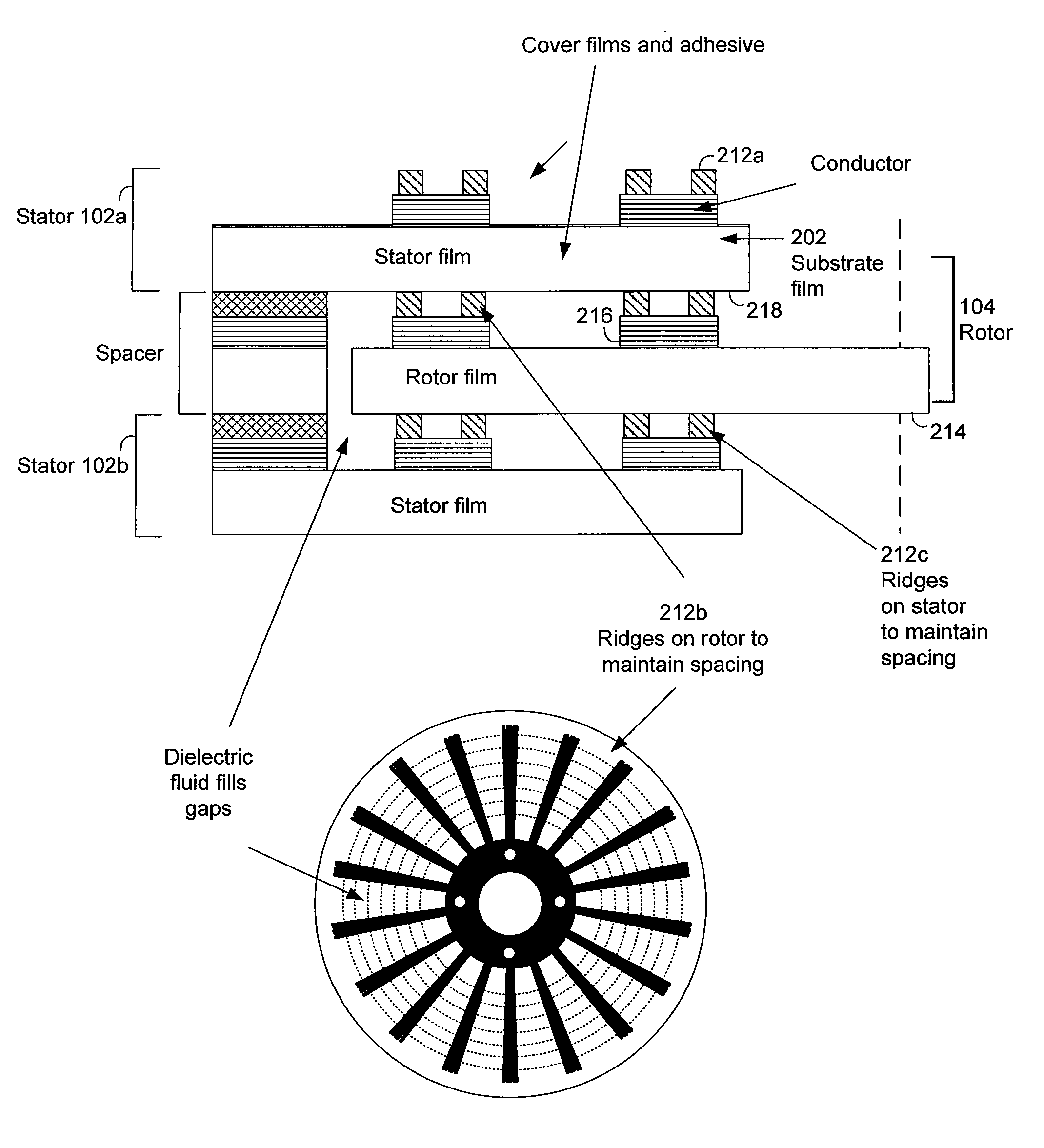
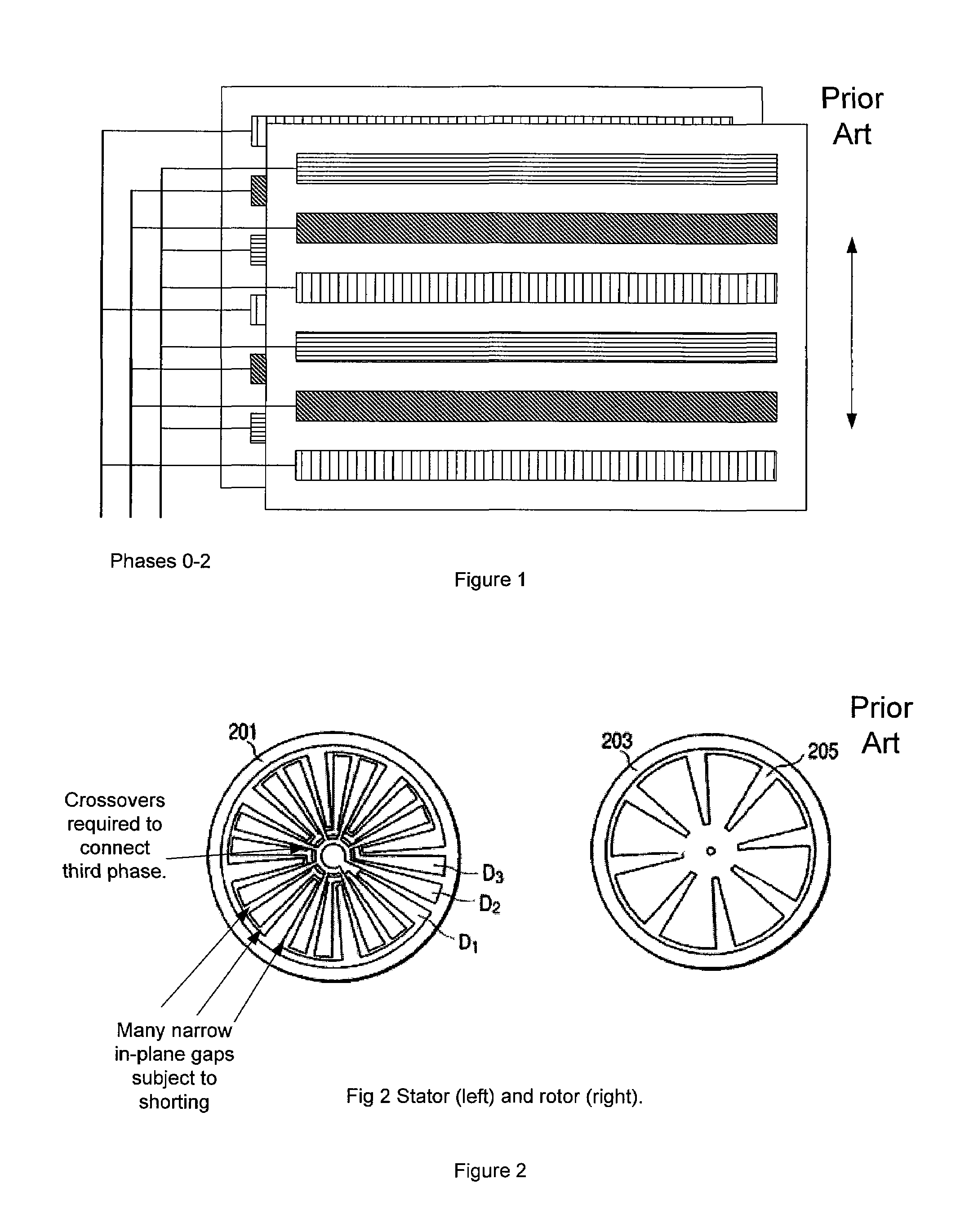
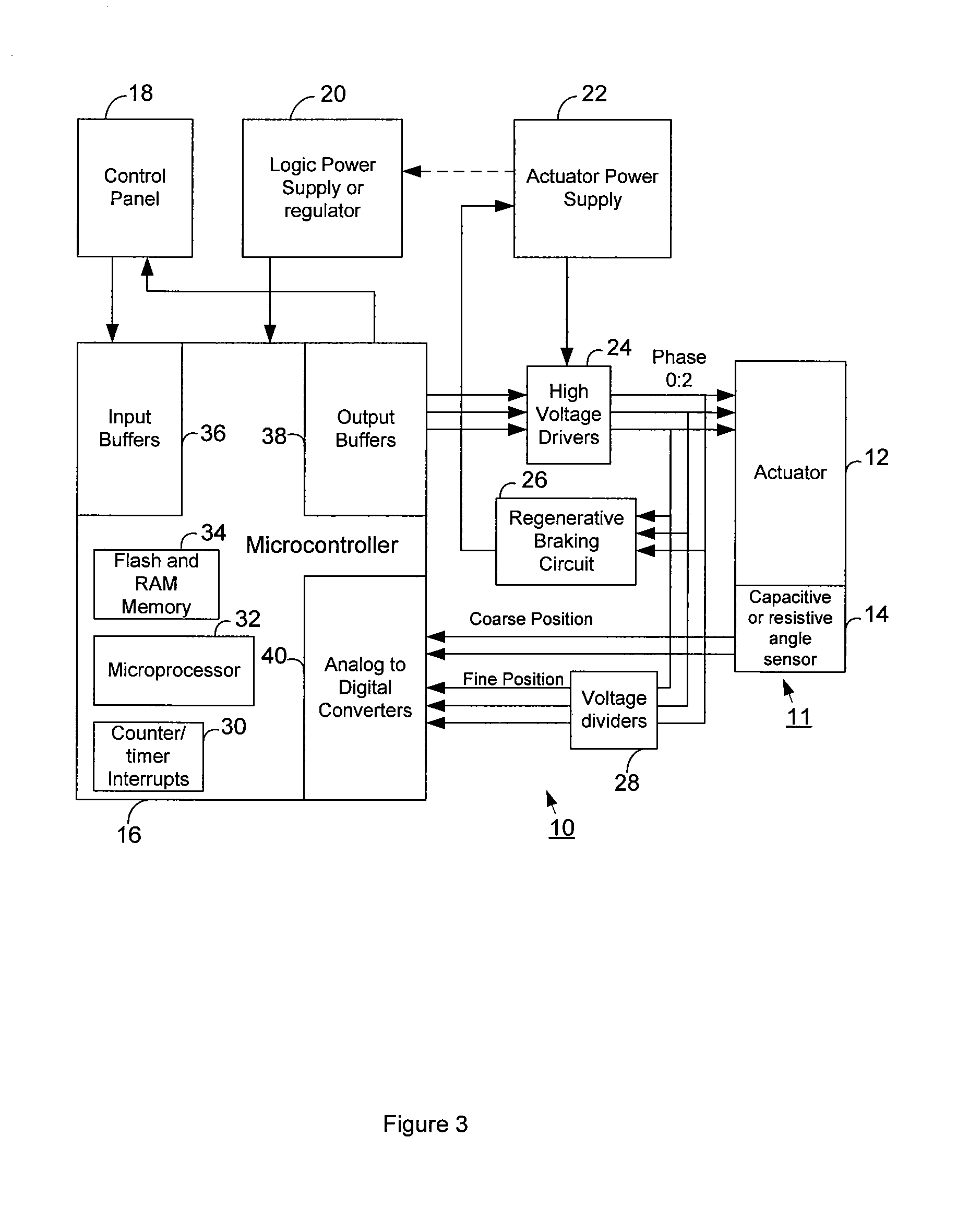
[0054]FIG. 3 is a block diagram of the electrostatic actuator assembly with the control system in accordance with the purpose of the invention. A power supply 22, typically a battery pack, supplies power to a microcontroller 16 that controls the operation of the actuator. The microcontroller 16 collects from the capacitive or resistive angle sensors 14 feedback information on the fine and coarse position of the actuator, and supplies control information that is used to drive the phases (0:1:2) with high voltages. A high voltage driver circuit 24 includes means for generating high voltages to drive the phases in response to low voltage control signals from the microcontroller. The high voltage circuit may also optionally include a regenerative braking circuit 26 to return power to the batteries 22 when the actuator 11 is driven by an external force.

[0055]The fine position sensor, to be discussed more fully later, has a voltage divider circuit 28 to allow...


PUM


Abstract

A high-power electrostatic actuator comprising rotor and stator layers with fault-tolerant electrode structures, a housing to contain the electrodes and dielectric fluid, and electronic circuitry driving a plurality of high-voltage phases. The actuator is constructed from multiple rotor and stator films separated by spacing elements. The electrode structure provides self-alignment for precise assembly. The actuator assembly includes built-in fine-position sensors to allow optimal timing in powering phases, and a coarse position sensor for feedback control. The electrode structure has a large region of linear force to provide low torque-ripple allowing simple high / low voltage pulsing instead of analog high voltage waveforms. Single or double sided flexible circuit manufacturing techniques are used to fabricate the rotor and stator films at low cost.

Description

REFERENCE TO PRIOR APPLICATION[0001]This application claims the benefit of U.S. Provisional Application Ser. No. 60 / 485,882 entitled “ELECTROSTATIC ACTUATOR WITH FAULT TOLERANT ELECTRODE STRUCTURE” filed Jul. 8, 2003.FIELD OF INVENTION[0002]The present invention related generally to actuators and, more specifically, to electrostatic actuators.BACKGROUND[0003]Most actuators currently in use, whether linear or rotary, are based on magnetic forces. The prior art linear actuators (typically solenoids) and rotary actuators (typically motors) require the use of magnetic materials such as iron, causing them to be heavy and unsuitable for applications that require high-power actuators with light weight.[0004]Motors also have the drawback that they operate efficiently at speeds of thousands of RPMs. Many applications require slow speed and high torque, and addressing these applications with electric motors requires additional gears, pulleys or other means to convert the motor's high speed an...

Claims


Application Information

Patent Timeline
Patent Type & Authority Patents(United States)
IPC IPC(8): H02N1/00H01L41/04H01L41/08H01L41/18H02N2/00
CPCH02N1/004
Inventor HORST, ROBERT W.
Owner ALTERG INC
Why Eureka
Try Eureka