Drive end-block for a rotatable magnetron

a technology of rotatable magnetron and end-block, which is applied in the direction of electrolysis components, vacuum evaporation coatings, coatings, etc., can solve the problems of known drive end blocks having a very complex design in general, and achieves the effects of less complexity, less manufacturing tolerances, and simple means

Inactive Publication Date: 2013-08-13
VON ARDENNE ANLAGENTECHNIK GMBH
View PDF13 Cites 3 Cited by
  • Summary
  • Abstract
  • Description
  • Claims
  • Application Information

AI Technical Summary

Benefits of technology

[0006]An improved drive end block is therefore to be provided, so that the requirements of the manufacturing tolerances of the components are lower than with known drive end blocks, the drive mechanism being electrically insulated from the parts carrying the process voltage as well as from the vacuum chamber, and the seal of the vacuum chamber being achievable with simpler means and less complexity.
[0010]According to another embodiment, it is possible to provide for a gear which is designed as a planetary gear, for example, to be arranged between the electric motor and the drive shaft. Planetary gears have a compact design and allow a coaxial arrangement of the motor and the drive shaft. The gear may be connected to the electric motor and / or to the drive shaft via one or each coupling.
[0013]For example, it is possible for the rotor of the electric motor to be arranged directly on the drive shaft, so that the drive shaft is at the same time the motor shaft of the electric motor. The entire drive unit may be designed to be more compact in this way.
[0016]In a further embodiment, it is possible for the end block housing not to have any opening toward the atmosphere. This embodiment has the advantage that vacuum sealing of the vacuum chamber is greatly facilitated. In this case, it is possible to omit the constant evacuation of the interior of the end block housing, which is customary and essential with the known drive end blocks. All that is necessary is a current feed-through for power supply to the electric motor.

Problems solved by technology

Known drive end blocks have a very complex design in general and require a large number of individual parts to protect the seal of the vacuum chamber against the atmosphere and the electric insulation of the components accessible from the outside.

Method used


Image

  • Drive end-block for a rotatable magnetron
  • Drive end-block for a rotatable magnetron
  • Drive end-block for a rotatable magnetron

Examples


Embodiment Construction

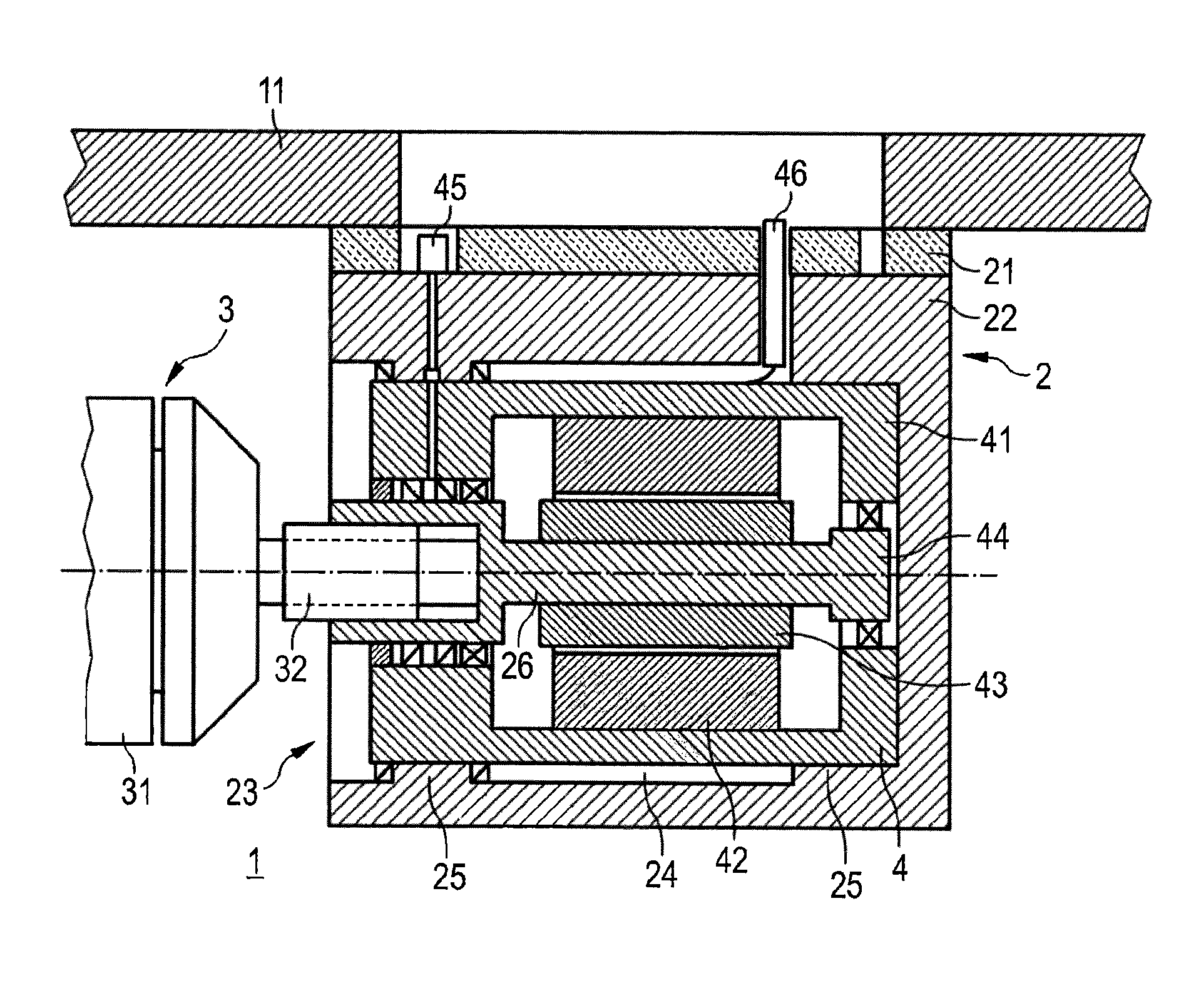
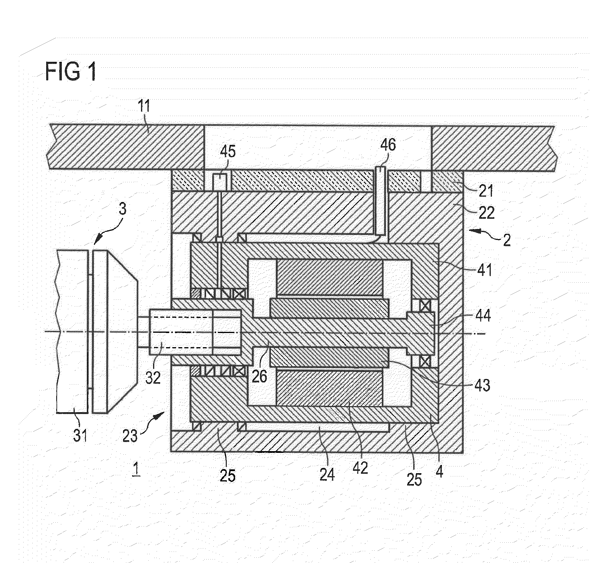
[0022]FIG. 1 shows a first exemplary embodiment of a drive end block in which the electric motor 4 is arranged inside the end block housing 22 and is coaxial with the drive shaft 26. In a vacuum chamber 1 a drive end block 2, to which is attached a rotating target 3 is arranged in a vacuum chamber 1, said target having a target tube 31 and a connecting piece 32, a magnet system (not visible in the drawing) being arranged in the interior of the target tube 31.

[0023]The drive end block 2 is detachably attached to a chamber wall 11 of the vacuum chamber 1 by means of an insulation element 21. The drive end block 2 comprises an end block housing 22 with an opening 23, which faces the interior of the vacuum chamber 1 and forms a hollow space 24. Two receptacles 25 for a drive unit corresponding to the cross-sectional contour of the auxiliary housing 41 of the drive unit are provided in this hollow space 24, so that the drive unit can be inserted into the hollow space 24 through the openi...


PUM

PropertyMeasurementUnit
torqueaaaaaaaaaa
electrically conductiveaaaaaaaaaa
timeaaaaaaaaaa

Abstract

A drive end block for a magnetron arrangement with a rotating target, comprises an end block housing having a rotatably mounted drive shaft. The drive shaft is arranged in the end block housing, accessible at an end from outside of the end block housing for connection to the rotating target, and adapted at its end inside the end block housing for introduction of a torque. An electric motor with a stator and a rotor for creating the torque is arranged inside the end block housing.

Description

CROSS REFERENCE TO RELATED APPLICATION[0001]This application claims priority of German application 10 2008 033 904.0 filed on Jul. 18, 2008, the entire contents of which is hereby incorporated herein by reference.BACKGROUND ART[0002]A drive end block for a magnetron arrangement with a rotating target that has a simple design and is easy to maintain is described hereafter.[0003]Magnetron arrangements with a rotating target are known in vacuum coating technology. With these magnetron arrangements, a target, usually tubular, surrounds a magnetic arrangement, such that the tubular target is rotatably mounted and drivable so that the target material is worn away uniformly. The tubular target is usually mounted between two end blocks in the vacuum chamber of a vacuum coating installation, said blocks being designed to allow rotatable mounting of the tubular target. In most cases, different functions are assigned to the two end blocks here. One of the end blocks is usually designed as a su...

Claims


Application Information

Patent Timeline
Patent Type & Authority Patents(United States)
IPC IPC(8): C23C14/34
CPCH01J37/3402H01J37/3435H01J37/3455
Inventor HEINRICH, HANS-JUERGENHAEHNE, SVEN
Owner VON ARDENNE ANLAGENTECHNIK GMBH
Why Eureka
Try Eureka