Zoom Lens System and Image Pick-Up Apparatus

a technology of zoom lens and image pickup, which is applied in the field of new zoom lens system and novel image pickup apparatus, can solve the problems of difficult miniaturization and achieve the effects of high magnification, high magnification, and high magnification zoom

Inactive Publication Date: 2008-12-18
SONY CORP
View PDF3 Cites 4 Cited by
  • Summary
  • Abstract
  • Description
  • Claims
  • Application Information

AI Technical Summary

Benefits of technology

[0011]Accordingly, in the zoom lens system of the present invention, miniaturization and high magnification can be realized. Moreover, in the image pick-up apparatus of the present invention, the zoom lens system of the present invention is used to thereby have to ability to realize miniaturized configuration thereof, and to have ability to perform photographing by high magnification over a range from the broad angle range side up to the telescopic range side.
[0012]Moreover, at least six lens groups are provided to change group spacings between the respective lens groups at the time of changing or adjusting magnification, thereby making it possible to attain compact and high magnification zoom lens system in which movement quantity of the lens entire system is relatively small. Further, the fourth lens group GR4 having small lens diameter is caused to be focus group to thereby permit the drive system of the focus group to be compact so that AF (Auto Focus) speed can be resultantly increased.
[0013]Further, in the image pick-up apparatus of the present invention, the zoom lens system of the present invention is used so that photographing by high magnification can be performed from the broad angle range up to the telescopic range although its configuration is small. In addition, convenience of use becomes satisfactory by high speed AF, and it becomes possible to precisely capture shutter chance.
[0014]In the inventions described in the claims 2 and 9, since the third and fifth lens groups GR3 and GR5 are moved in one body along on the optical axis in magnification changing or adjusting operation, the third, the fourth and the fifth lens groups GR3, GR4 and GR5 can be constituted by single cam cylinder. If there is employed a configuration to move the fourth lens group GR4 serving as the focus group thereamong, not only mechanical configuration becomes easy, but also relative positioning of the third, the fourth and the fifth lens groups GR3, GR4 and GR5 which are apt to be rigorous in tolerance in manufacturing becomes easy.

Problems solved by technology

However, the zoom lenses described in the Japanese Patent Application Laid Open No. 1992-146407 publication and the Japanese Patent Application Laid Open No. 1999-174324 publication relate to exchange lens of single-lens reflex camera, etc., and are difficult in miniaturization and realization of broad angle because long back-focus for arrangement space of mirror for jumping up mirror, etc. must be ensured.

Method used


Image

  • Zoom Lens System and Image Pick-Up Apparatus
  • Zoom Lens System and Image Pick-Up Apparatus
  • Zoom Lens System and Image Pick-Up Apparatus

Examples


first embodiment

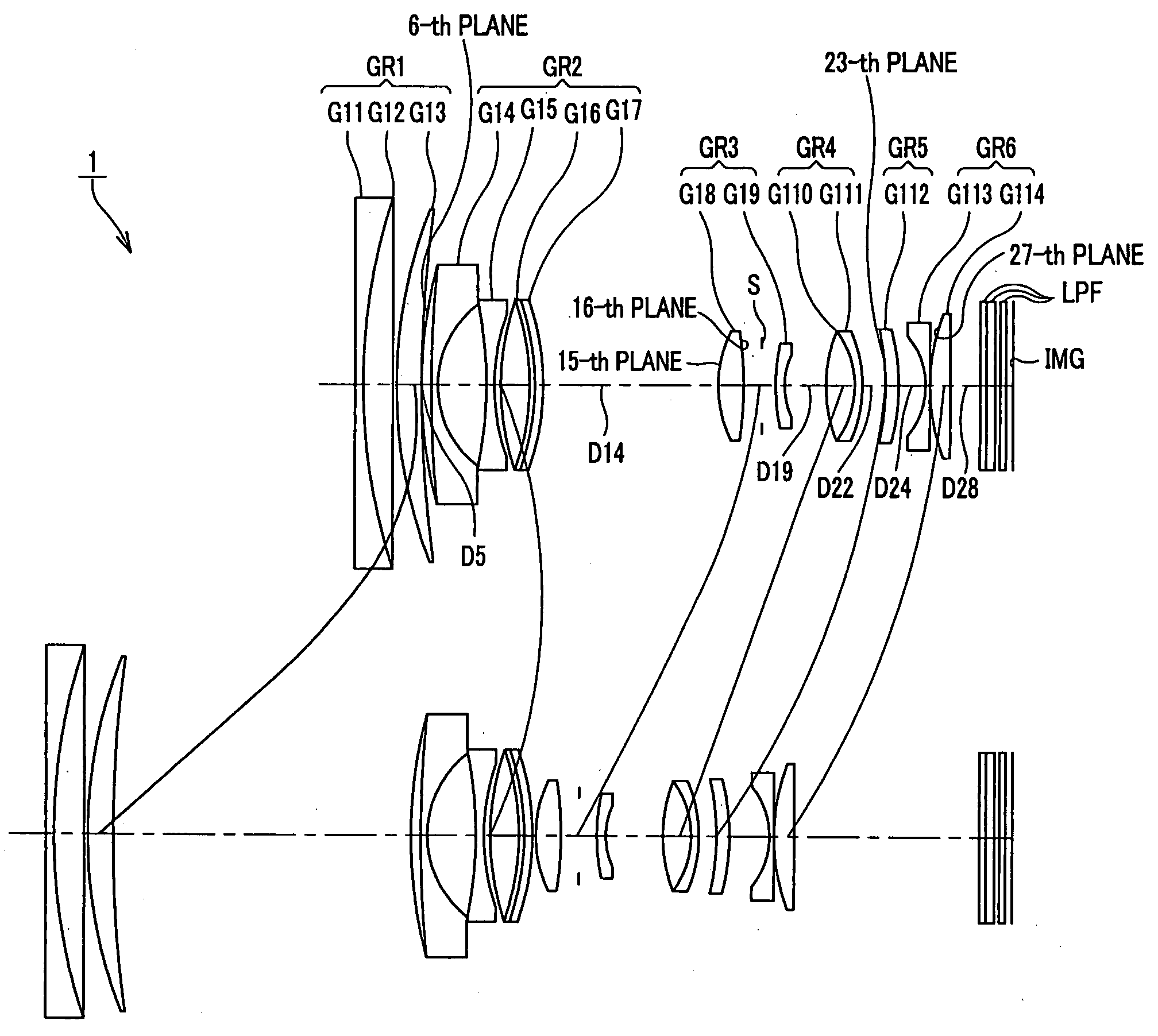
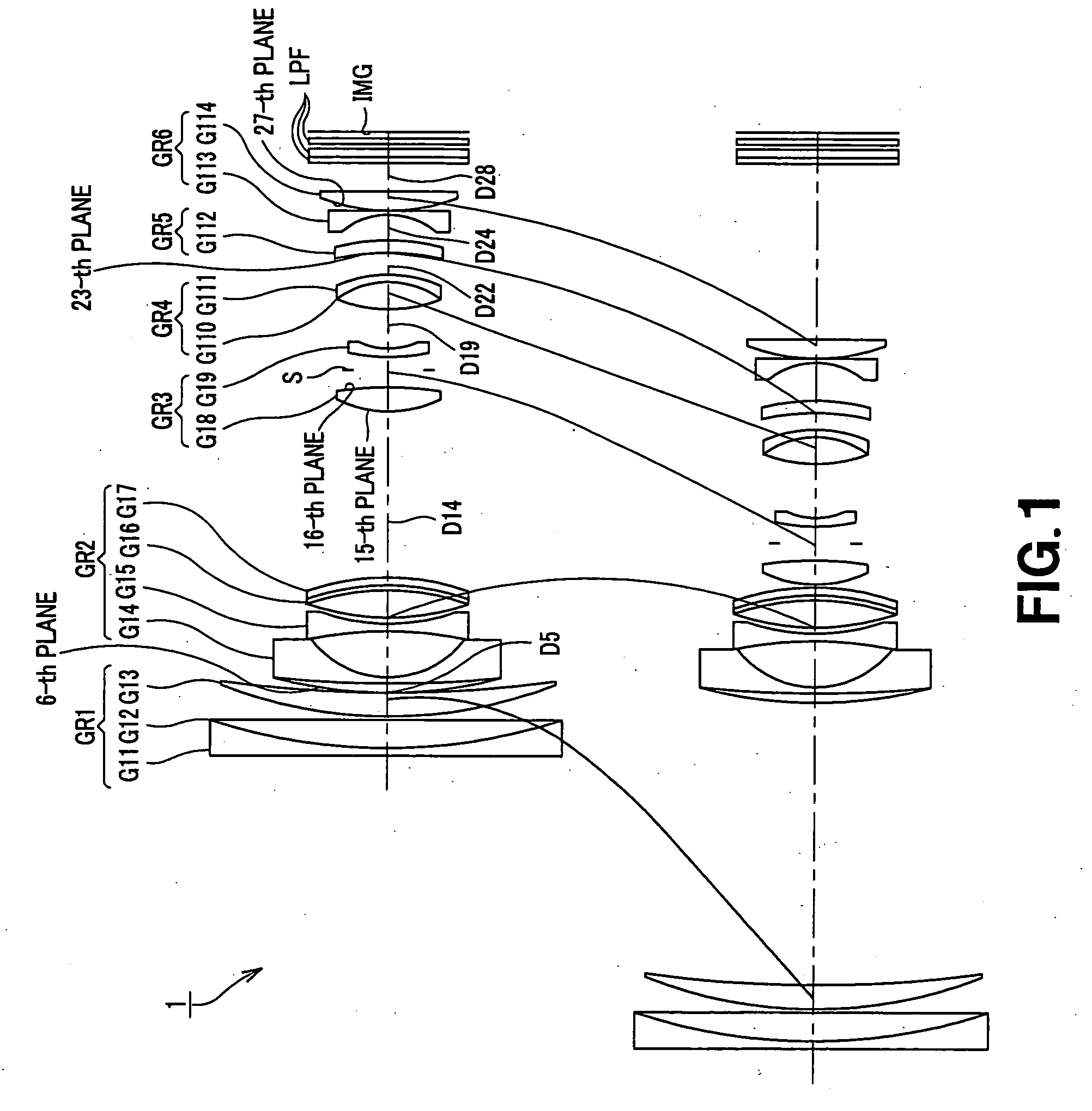
[0061]FIG. 1 shows the lens configuration according to the zoom lens system of the present invention. There are arranged, in order from the object side, a first lens group GR1 having positive refractive power, a second lens group GR2 having negative refractive power, a third lens group GR3 having positive refractive power, a fourth lens group GR4 having positive refractive power, a fifth lens group GR5 having negative refractive power, and a sixth lens group GR6 having negative refractive power. In magnification changing or adjusting operation from the wide-angle end state up to the telescopic end state, the respective lens groups are moved on the optical axis as indicated by solid lines from the state shown at the upper row of FIG. 1 to the state shown at the lower row.

[0062]The first lens group GR1 is composed of a connection lens of a negative lens G11 and a positive lens G12 which are arranged in order from the object side. The second lens group GR2 is composed of a negative len...

embodiment 1

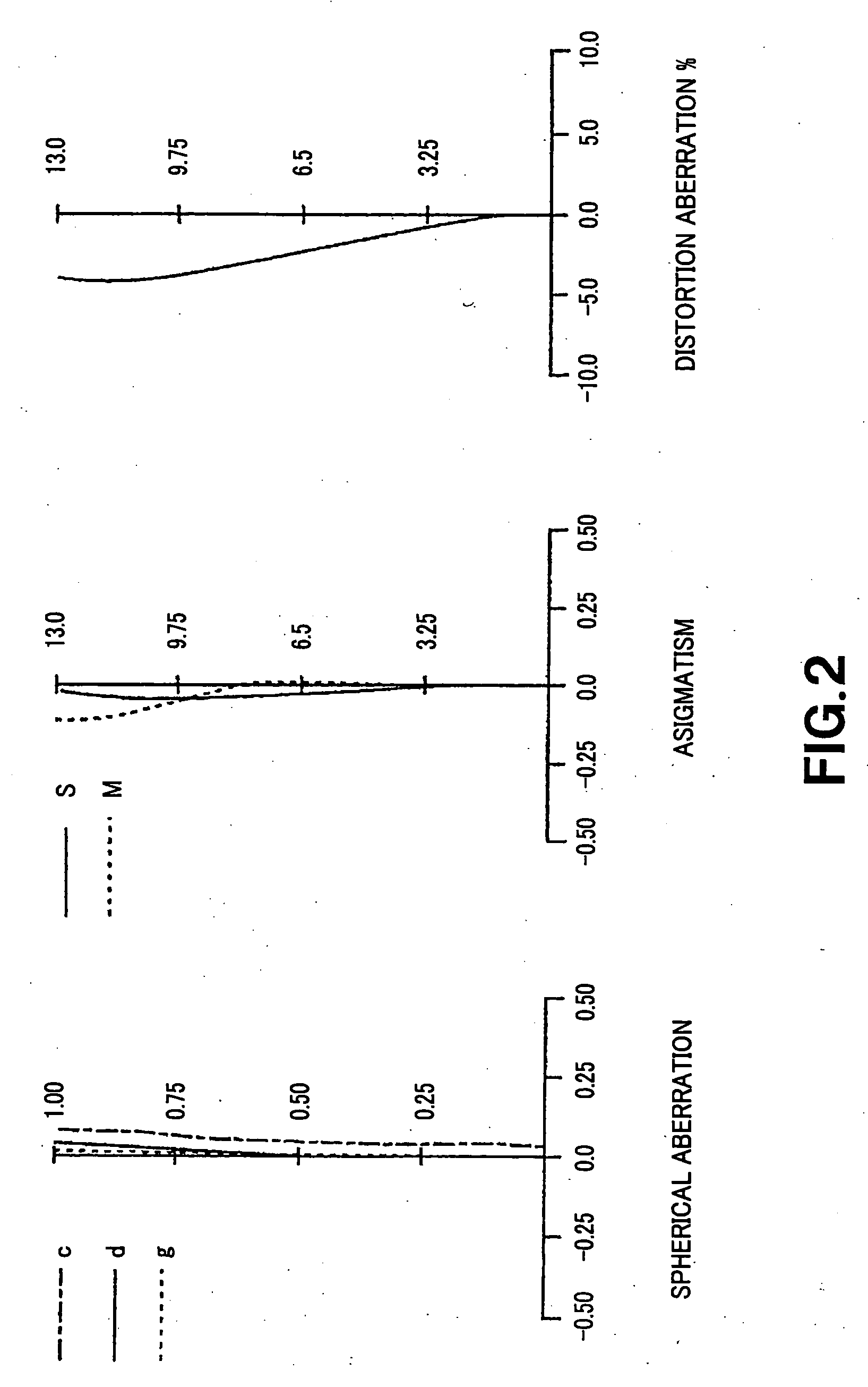
[0067]Various aberration diagrams in the infinity far in-focus state of the numeric value embodiment 1 are respectively shown in FIGS. 2 to 4. FIG. 2 shows various aberration diagrams at wide-angle end state (f=14.74). FIG. 3 shows various aberration diagrams at intermediate focal length (f=33.96) between wide-angle end state and the telescopic end state, and FIG. 4 shows various aberration diagrams at the telescopic end state (f=78.21)

[0068]In the respective aberration diagrams of FIGS. 2 to 4, in the case of the spherical aberration, ratio with respect to open F-value is taken on the ordinate and defocus is taken on the abscissa, wherein solid line indicates spherical aberration at d line, single-dotted lines indicate spherical aberration at C line, and dotted lines indicate spherical aberration at g line. In the case of astigmatism, image height is taken on the ordinate and the focus is taken on the abscissa, wherein solid line S indicates of sagittal image and dotted lines M ind...

embodiment 2

[0075]Various aberration diagrams in the infinity far in-focus state of the numeric value embodiment 2 are respectively shown in FIGS. 6 to 8. FIG. 6 shows various aberration diagrams at the wide-angle end state (f=14.73), FIG. 7 shows various aberration diagrams at intermediate focal length (f=33.94) between the wide-angle end state and the telescopic end state, and FIG. 8 shows various aberration diagrams at the telescopic end state (f=78.21).

[0076]In the respective aberration diagrams of FIGS. 6 to 8, in the case of the spherical aberration, the ordinate indicates ratio with respect to open F-value, the abscissa indicates defocus, solid line indicates spherical aberration at d-line, single dotted lines indicate spherical aberration at C line, and dotted lines indicate spherical aberration at g-line. In the case of astigmatism, the ordinate indicates image height, the abscissa indicates focus, solid line S indicate sagittal image surface, and dotted lines M indicates meridional im...


PUM


Abstract

There is provided a zoom lens system, compact and light in weight and having high image formation performance over the zoom entire range irrespective of object lens while covering the range from the broad angle side up to the telescopic end state side, which is used in video camera and/or digital still camera. A zoom lens system at least includes a first lens group GR1 having positive refractive power, a second lens group GR2 having negative refractive power, a third lens group GR3 having positive refractive power, a fourth lens group GR4 having positive refractive power, a fifth lens group GR5 having weak refractive power (including refractive power=0), and a sixth lens group GR6 having negative refractive power which are arranged in order from the object side to change spacings between the respective lens groups to thereby perform magnification changing or adjusting operation, wherein when group spacing between the i-th lens group and the j-th lens group at the wide-angle end state is DW(i-j), and group spacing between the i-th lens group and the j-th lens group at the telescopic end state is DT(i-j), the following conditional formulas (1), (2) and (3) are satisfied, and the fourth lens group GR4 is moved in the optical axis direction so that focusing operation is performed.
DW(1−2)<DT(1−2)   (1)
DW(2−3)>DT(2−3)   (2)
DW(5−6)>DT(5−6)   (3)

Description

TECHNICAL FIELD[0001]The present invention relates to a novel zoom lens system and a novel image pick-up apparatus. More particularly, the present invention relates to a zoom lens system having excellent compactness and having high image formation performance irrespective of object distance while covering the range from the broad angle side up to the telescopic side, which is suitable for photographing optical system of digital input / output equipment such as digital still camera and / or digital video camera, etc.; and an image puck-up apparatus comprising such a zoom lens system.[0002]This Application claims priority of Japanese Patent Application No. 2005-068933, filed on Mar. 11, 2005, the entirety of which is incorporated by reference herein.BACKGROUND ART[0003]In recent years, image pick-up apparatuses using solid-state image pick-up devices such as digital still camera, etc. are being popularized. Especially, with popularization of digital still camera, there is required a zoom ...

Claims


Application Information

Patent Timeline
Patent Type & Authority Applications(United States)
IPC IPC(8): H04N5/262
CPCG02B15/173G02B15/1461G02B13/009G02B15/22G02B3/0087G02B3/04G03B17/12H04N23/55
Inventor SUEYOSHI, MASAFUMIKURODA, DAISUKE
Owner SONY CORP
Why Eureka
Try Eureka