Distance-controlled tunneling transducer and direct access storage unit employing the transducer

Inactive Publication Date: 2000-03-07
IBM CORP
View PDF12 Cites 22 Cited by
  • Summary
  • Abstract
  • Description
  • Claims
  • Application Information

AI Technical Summary

Problems solved by technology

Because of the fact that the operating distances in tunneling as well in in field-emission environments are so small, it may even happen that the tip crashes into a surface it and thus suffers damage, unless some measure is taken to maintain the tip-to-surface distance essentially constant.
While it is acknowledged that the idea has occurred to integrate the tunnel tip feedback loop into the semiconductor chip on which the tunnel tip is formed, it has turne

Method used


Image

  • Distance-controlled tunneling transducer and direct access storage unit employing the transducer
  • Distance-controlled tunneling transducer and direct access storage unit employing the transducer
  • Distance-controlled tunneling transducer and direct access storage unit employing the transducer

Examples


Embodiment Construction

While the invention will be described in connection with the electrostatic deflection of a cantilever beam as conventionally used in micromechanical arrays, it will be obvious to those skilled in the art that the invention is also applicable to piezoceramic scanners.

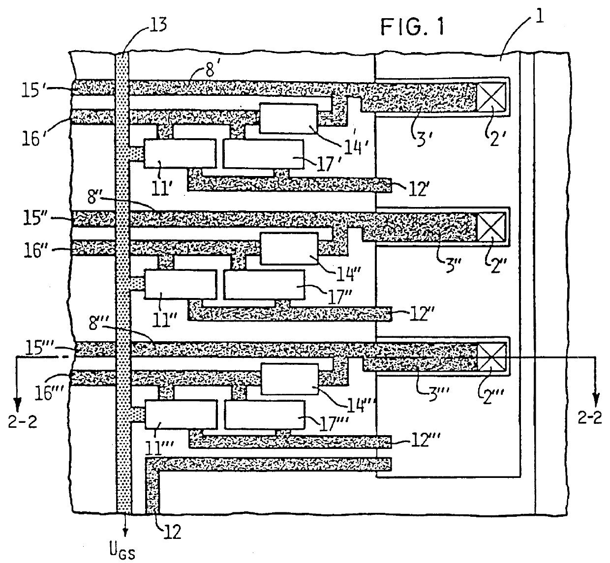
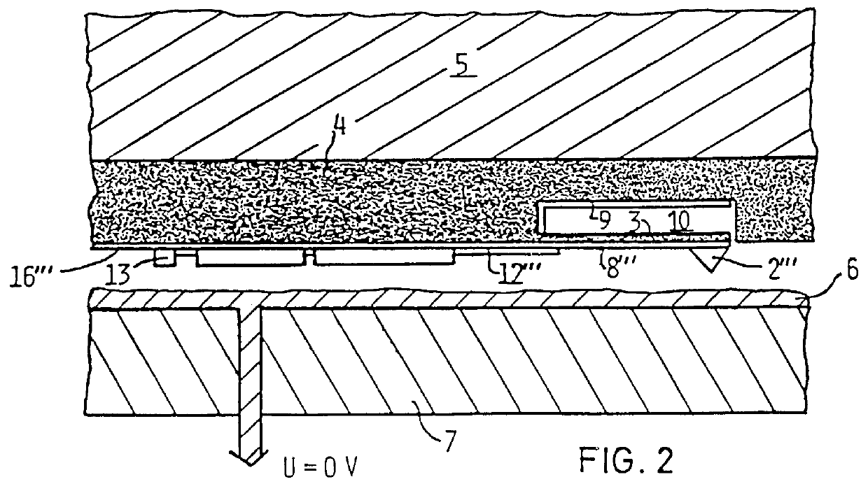
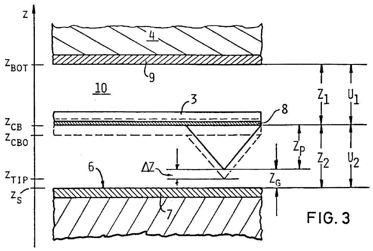
FIGS. 1 and 2 show the contemplated arrangement of the elements of the transducer in accordance with the invention in a semi-schematical way. Referring to FIG. 1, there is shown a section of the transducer 1 with three tunnel tips 2', 2", 2"' out of a plurality of tunnel tips (or field-emission tips) arranged in an array. The tunnel tips are attached to cantilever beams 3',3",3"' respectively which are formed, e.g. by etching from body 4, FIG. 2, of transducer 1 as an integral part thereof. Transducer 1 is mounted to a conventional xyz-drive 5 which provides lateral deflection as well as coarse approach and adjustment of the average distance between tunnel tip 2 and the oppositely disposed surface 6, by keeping the total...


PUM


Abstract

A distance-controlled tunneling transducer comprises a plurality of tunnel tips arranged in an array at a tunneling distance from an electrically conductive surface of a storage medium. Each tip is attached to a respective cantilever beam permitting the distance between each tip and the surface to be individually pre-adjusted electrostatically. Arranged in juxtaposition with each cantilever beam is an active control circuit for adjusting the tip-to-surface distance during operation of the storage unit, thus preventing crashes of the associated tip into possible asperities on the surface of the recording medium. Each control circuit is designed such that its operating voltage concurrently serves to pre-adjust its associated cantilever beam and to maintain the tip-to-surface distance essentially constant.

Description

BACKGROUND OF THE INVENTIONThe present invention relates to a distance-controlled tunneling transducer for use in a direct storage unit, having a plurality of tunnel tips arranged facing a recording medium. In particular the invention teaches improved gap control means for implementation in micromechanical techniques. The invention is also applicable to low-voltage field-emission environments where the gap dimension is somewhat larger in the tunneling regime. Therefore, where in the following description reference is made to tunneling phenomena, those skilled in the art will be able to easily apply what is said to field-emission phenomena as well.In the tunneling regime, the tip / surface distance typically is less than 2 nm, and in the field-emission environment, that distance is considered to be on the order of 20 nm. Small local deviations from planarity of the surface of the recording medium, say on the order of tenths of a nanometer, may result in relatively large changes of the ...

Claims


Application Information

Patent Timeline
IPC IPC(8): G11B9/00G11B9/08G11B5/00G11B5/012
CPCG11B9/14G11B9/1445G11B9/1454B82Y10/00G11B5/00G11B5/012G11B9/08
Inventor POHL, WOLFGANG D.SCHNEIKER, CONRAD W.
Owner IBM CORP
Why Eureka
Try Eureka