
Water distribution plate for rotating sprinklers

Active Publication Date: 2007-07-10
HUNTER INDUSTRIES
View PDF12 Cites 55 Cited by
  • Summary
  • Abstract
  • Description
  • Claims
  • Application Information

AI Technical Summary

Benefits of technology

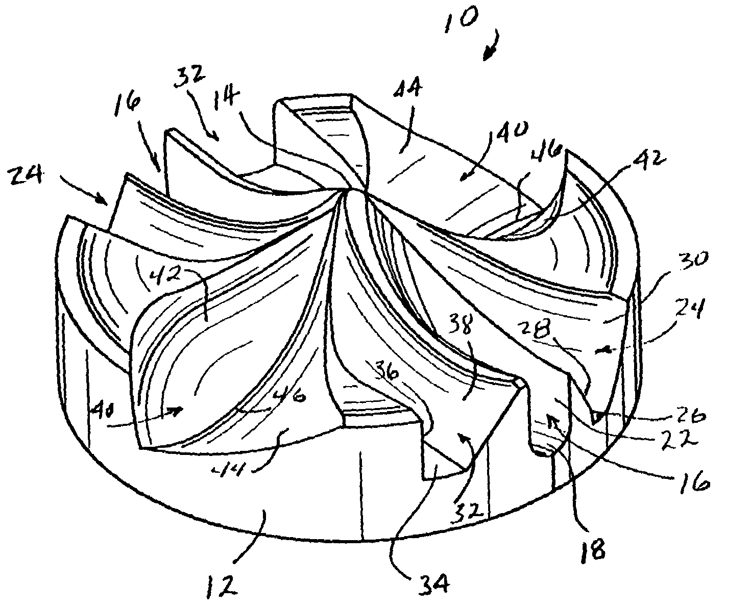
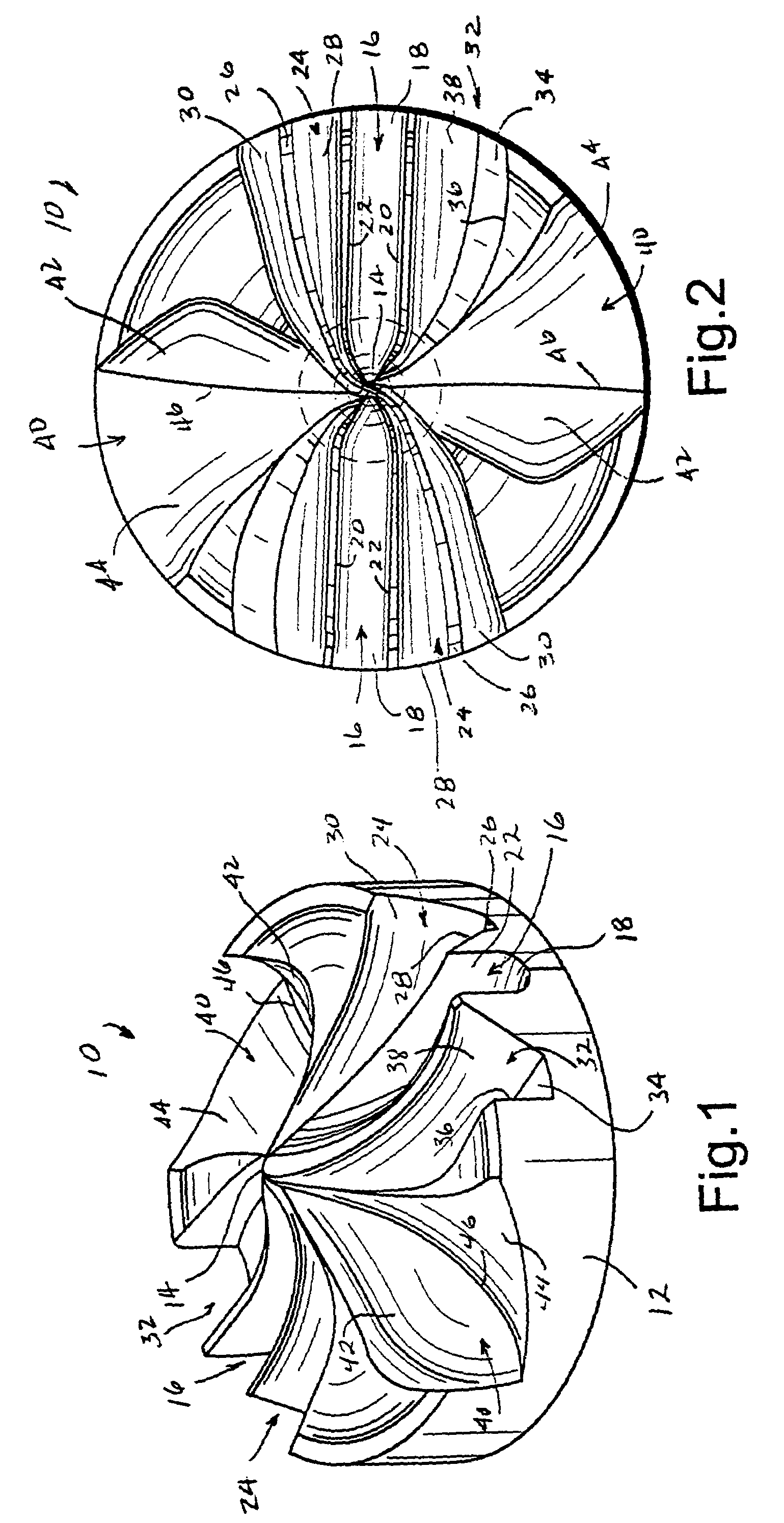
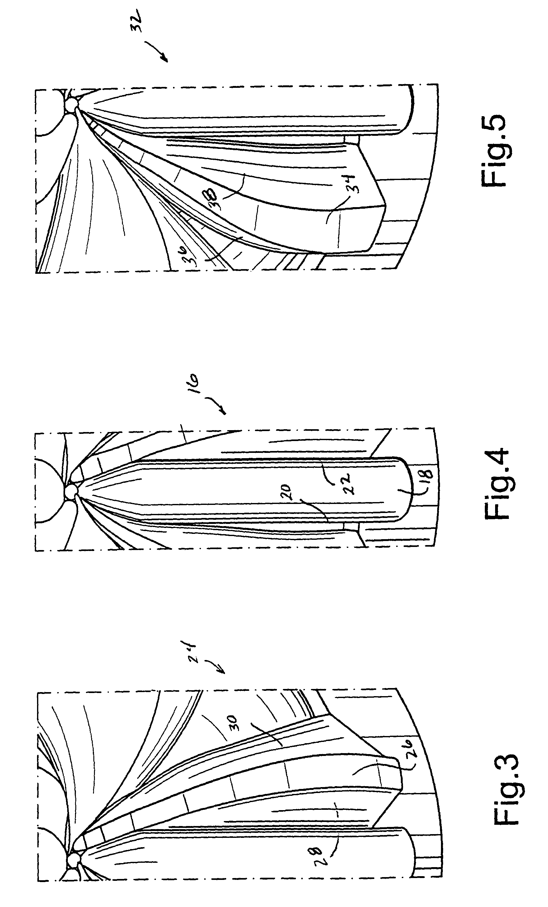
[0008]In one exemplary embodiment of the present invention, a water distribution plate, or rotor plate, includes a surface incorporating individual pairs of channels that are shaped to perform different functions. A first pair of channels (referred to as “drive channels”) causes the plate to rotate when impinged by a stream emitted from a nozzle. A second pair of channels (referred to as “brake channels”) tends to slow rotation of the plate, while a third set of channels (referred to as “range channels”) is substantially neutral with respect to plate rotation but increases the range or throw radius of the stream. Two additional but larger channels (referred to as “fill channels”) serve primarily to fill in the pattern between the sprinkler and the maximum stream throw radius. By separating the functions of drive, range, and braking in various channels, it is possible to enhance desirable performance parameters including radius of throw, distribution pattern, and consistency of rotation speeds.
[0011]The range channels lie between adjacent drive and brake channels, and are also generally diametrically opposite each other. Each range channel has a substantially V-shaped cross-section at its radially innermost or entrance point, quickly transitioning to a substantially U-shaped cross-section for substantially its entire length, with upwardly curved side walls tapering outwardly from the center for only a short radial distance, and then exhibiting a substantially constant width to the exit location in the peripheral wall. These channels provide tight streams with maximum radius of throw and good wind fighting capability.
[0012]The brake channels are also generally diametrically opposed to each other, and are generally similar in cross-section to the drive channels, but they are oppositely curved and the flat bottom has a slightly greater width. In addition, the radially inner portions of the brake channels are smaller in cross-section than the radially inner portions of the drive channels. This means that the drive channels carry larger volumes of the stream at smaller nozzle sizes. For larger nozzles, the drive and brake channels have comparable flows. This arrangement helps counteract the tendency of the plates to rotate faster with larger nozzles.

Problems solved by technology

A disadvantage of the prior designs is that the radial distribution pattern has a smaller throw radius than if the grooves were straight and on center.
Another disadvantage is the difficulty in maintaining a generally consistent rotation speed over a flowrate and pressure range.

Method used


Image

  • Water distribution plate for rotating sprinklers
  • Water distribution plate for rotating sprinklers
  • Water distribution plate for rotating sprinklers

Examples


Embodiment Construction

[0028]With reference initially to FIGS. 1, 2, 6 and 7, the water distribution plate 10 in accordance with a first exemplary embodiment is a circular, disk-like component with an outer peripheral edge 12. The operative side of the plate is generally “cone-shaped” at the center, with an apex 14 that, when mounted in a sprinkler assembly, is closest the water discharge orifice of the sprinkler nozzle. From the apex 14 (coinciding with the vertical center axis of the plate 10), the various channels extend outwardly to the peripheral edge 12, with the entrance to each of the drive and brake channels in the apex region being slightly offset from the center axis of the plate (best seen in FIG. 2).

[0029]A primary stream from a fixed nozzle (not shown) impinges on the plate in the apex region and is split into several secondary streams that transition from a substantially vertical orientation to a substantially horizontal orientation for radial distribution via the channel exits. In this emb...


PUM


Abstract

A rotor plate for a sprinkler includes a water impingement surface bounded by an annular peripheral wall and having a radial center, and adapted to be impinged upon by a stream emitted from a nozzle. The water impingement surface is formed to include at least one radially extending drive channel having an entrance proximate the radial center and an exit in the peripheral wall, the drive channel curving from entrance to exit in a first direction so as to cause the plate to rotate when the stream exits at an offset from the center of rotation; at least one range channel extending substantially radially with little or no curving, from entrance to exit; and at least one brake channel curving from entrance to exit in a second direction opposite the first direction to thereby resist rotation of the plate caused by at least one drive channel.

Description

[0001]This application is a division of application Ser. No. 09 / 982,084, filed Oct. 19, 2001 now U.S. Pat. No. 6,688,539, the entire content of which is hereby incorporated by reference in this application.BACKGROUND OF THE INVENTION[0002]This invention relates tp water distribution for irrigation purposes and, more particularly, to a water distribution plate for a rotatable sprinkler head.[0003]Sprinkler heads of the type disclosed in U.S. Pat. No. 4,660,766 include a sprinkler body or housing having an inlet which is adapted to be connected to a source of water under pressure. The outlet is defined by a nozzle that directs the water under pressure communicating with the sprinkler body as a primary stream into the atmosphere along a generally vertically extending axis. A rotary water distribution plate (also referred to as a “rotor plate”) is provided for receiving the primary stream and directing it outwardly in a circular distribution pattern. A viscous damper mechanism is provid...

Claims


Application Information

Patent Timeline
IPC IPC(8): B05B1/00B05B1/26B05B1/34B05B15/00B05B3/04
CPCB05B3/0486
Inventor GRIEND, LOREN VANDER
Owner HUNTER INDUSTRIES
Learn More