
Semiconductor device and display element using semiconductor device

a semiconductor and display element technology, applied in non-linear optics, instruments, optics, etc., can solve the problems of adversely affecting electronic characteristics, limited use of sog film as an interlayer insulation film,

Inactive Publication Date: 2007-07-10
SEMICON ENERGY LAB CO LTD
View PDF91 Cites 45 Cited by
  • Summary
  • Abstract
  • Description
  • Claims
  • Application Information

AI Technical Summary

Benefits of technology

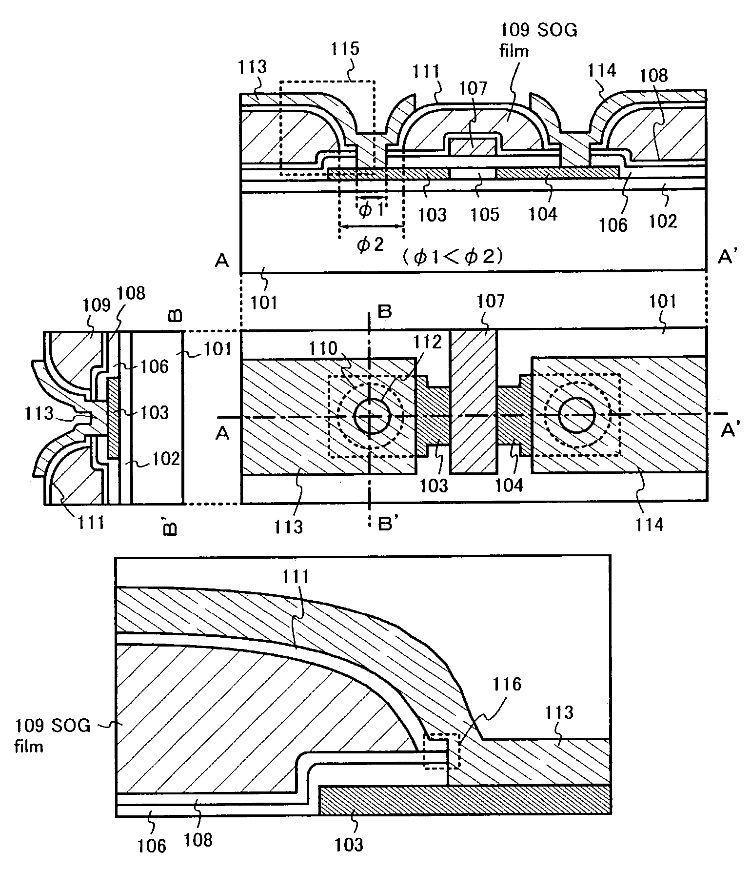
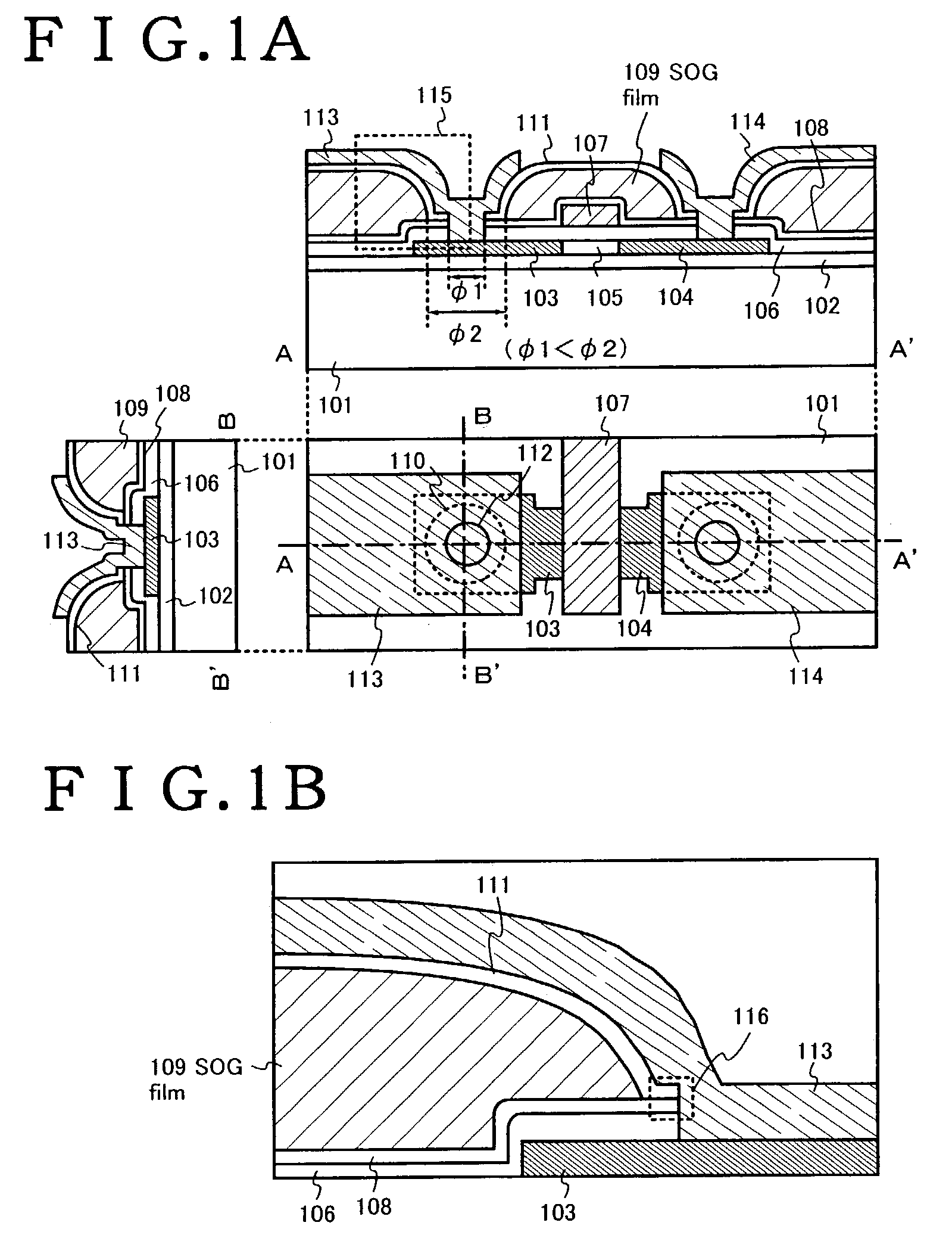
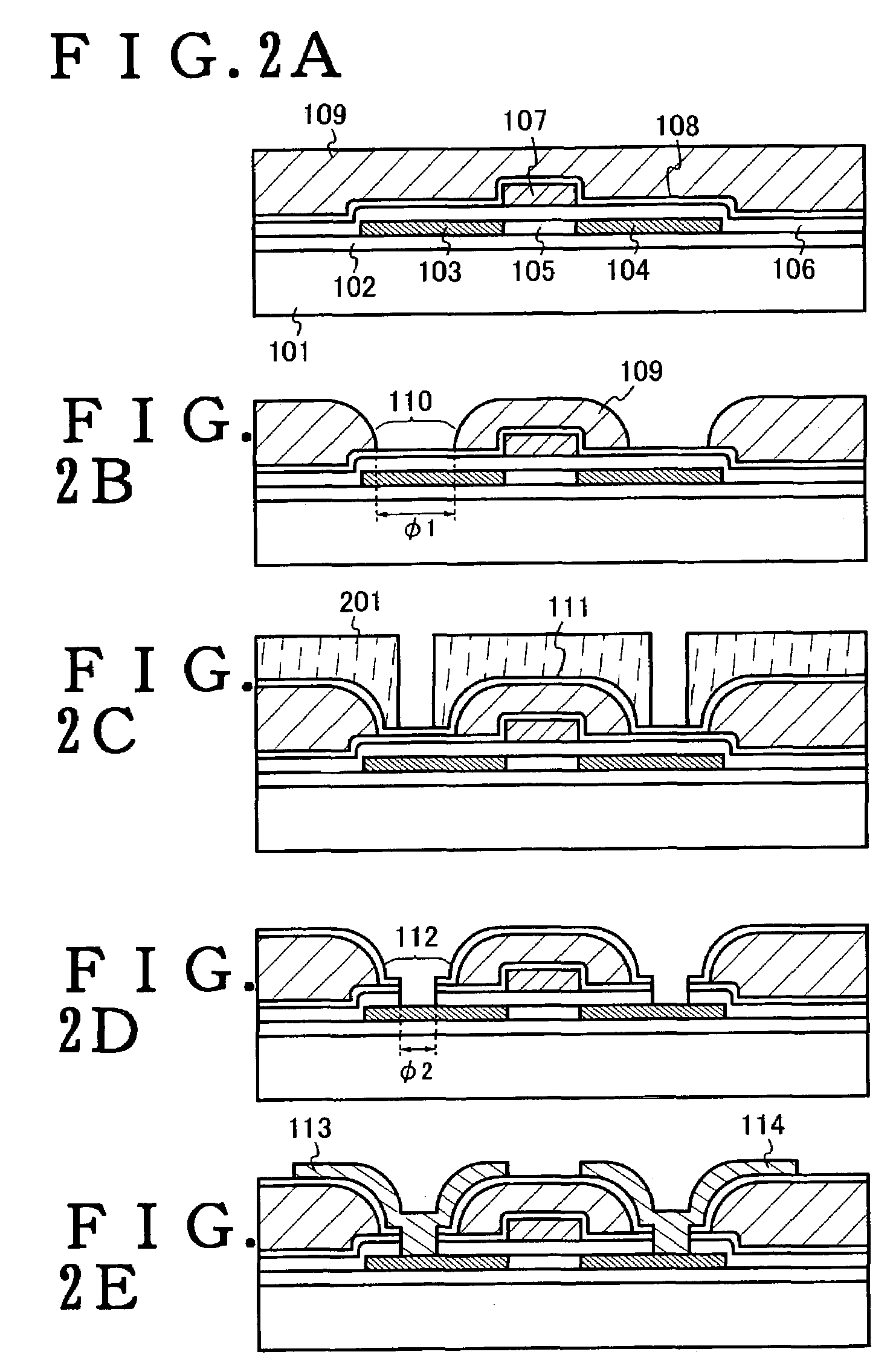
[0009]The present invention is characterized by achieving the above-mentioned objects by following means. That is, in a display device using an SOG film as an insulation film for leveling surface irregularities attributed to semiconductor- devices, particularly transistors (hereinafter, the insulation film being referred to as “leveling film”), an improvement is characterized in that the SOG film is formed as a leveling film on a first inorganic insulation film formed such that the first inorganic insulation film covers the semiconductor devices, first openings are formed in the leveling film and, thereafter, a second inorganic insulation film is formed such that the second insulation film covers the first openings, second openings are formed in the second inorganic insulation film newly using a photo resist or the like, and upper electrodes and lower electrodes which are present while sandwiching the leveling film therebetween are electrically connected to each other. Further, the present invention is also characterized by using a nitride insulation film as the first inorganic insulation film or the second inorganic insulation film.

Problems solved by technology

However, it has been known that the SOG film has water permeability and water retentivity and hence, use of SOG film as an interlayer insulation film is limited.
This is because that when the SOG film is used as the interlayer insulation film, the SOG film allows moisture or the like to pass therethrough so that there is a fear that the moisture or the like adversely affects electronic characteristics (particularly leaking current or the like) of a transistor formed below the SOG film.
Further, even with an interlayer insulation film having a laminar structure which sandwiches the SOG film between other insulation films formed by a plasma CVD (Chemical Vapor Deposition) method or the like, for example, the SOG film is exposed in a cross section of a contact hole (also referred to as “via”) so that there arises a problem of a so-called poisoned via which forms a moisture supply source and erodes wiring or the like.

Method used


Image

  • Semiconductor device and display element using semiconductor device
  • Semiconductor device and display element using semiconductor device
  • Semiconductor device and display element using semiconductor device

Examples


embodiment 1

[0046]In this embodiment, an example in which the formation position of the first opening portion 110 is changed in FIGS. 1A and 1B will be described using FIGS. 3A and 3B. Note that FIGS. 3A and 3B each show a cross sectional structure immediately after the formation of the second opening portion. In addition, the reference symbols used in FIGS. 1A and 1B are used to describe if necessary.

[0047]In FIG. 3A, reference numeral 301 denotes a first opening portion having a diameter of φ1 and 302 denotes a second opening portion having a diameter of φ2. A characteristic in FIG. 3A is that the first opening portion 301 is provided to protrude from the end portion of the source region 103. The SOG film 109 can be formed in a position as indicated in this embodiment because the first passivation film 108 becomes an etching stopper, thereby stopping the progress of etching. In addition, in FIG. 3B, reference numeral 303 denotes a first opening portion having a diameter of φ3 and 304 denotes ...

embodiment 2

[0049]In this embodiment, an example in which the present invention is applied to a light emitting device such as an EL display device will be described. FIG. 5A is a top surface view of a pixel of the light emitting device (note that a state up to the formation of a pixel electrode is indicated), FIG. 5B is a circuit diagram thereof, arid FIGS. 5C and 5D each are a cross sectional view along a line A–A′ or B–B′.

[0050]As shown in FIGS. 5A and 5B, a display portion of the light emitting device includes a plurality of pixels which are surrounded by gate wirings 551, data wirings 552, and power source wirings (wirings for supplying a constant voltage or a constant current) 553 and arranged in matrix. In each of the pixels, a TFT 554 serving as a switching element (hereinafter referred to as a switching TFT), a TFT 555 serving as means for supplying a current or a voltage for producing light emission of an EL element (hereinafter referred to as a driver TFT), a capacitor portion 556, an...

embodiment 3

[0071]In this embodiment, an example is indicated in which a connection structure between the drain wiring 521 and the pixel electrode 558 is modified in the light emitting device described in Embodiment 2. Note that the fundamental structure is not changed as compared with that shown in FIG. 5C. Thus, in this embodiment, reference symbols are provided to only necessary portions and the description will be made.

[0072]As shown in FIG. 8A, a pixel electrode 801 made from an oxide conductive film is formed and then a drain wiring 802 is formed, so that a structure in which the drain wiring 802 is in contact with the pixel electrode 801 so as to cover the end portion thereof is obtained. When such a structure is obtained, the pixel electrode 801 may be formed after the formation of a second opening portion 803. Alternatively, the second opening portion 803 may be formed after the formation of the pixel electrode 801. In any case, even when dry etching processing is conducted, the SOG fi...


PUM

PropertyMeasurementUnit
widthaaaaaaaaaa
contact lengthaaaaaaaaaa
dielectric constantaaaaaaaaaa

Abstract

The present invention achieves the enhancement of stability of operational performance of a display device and the enlargement of margin of design in circuit designing. In a semiconductor device including a semiconductor, a gate insulation film which is brought into contact with the semiconductor, a gate electrode which faces an active layer by way of the gate insulation film, a first inorganic insulation film which is formed above the active layer, an SOG film which is formed on the first inorganic insulation film, and a second inorganic insulation film which is formed on the SOG film, and wiring which is formed on the second inorganic insulation film, an inner wall surface of a first opening portion formed in the SOG film is covered with the second inorganic insulation film and, at the same time, a second opening portion which is formed in a laminated body including the gate insulation film, the first inorganic insulation film and the second inorganic insulation film is provided to the inside of the first opening portion, and the semiconductor and the wiring are connected to each other through the first opening portion and the second opening portion.

Description

BACKGROUND OF THE INVENTION[0001]1. Field of the Invention[0002]The present invention relates to a semiconductor device (typically transistor) and a manufacturing method thereof, and more particularly the present invention belongs to a technical field of a display device using thin film transistors as devices. That is, the present invention belongs to a technical field relating to a display device represented by a liquid crystal display device or an electroluminescence display device or the like, a technical field relating to a sensor represented by a CMOS sensor or the like, or a technical field relating to all semiconductor devices mounting other semiconductor integrated circuits.[0003]2. Description of the Related Art[0004]Recently, the development of a liquid crystal display device and an electroluminescence display device which integrates thin film transistors (TFTs) on a glass substrate has been in progress. Either one of these display devices constitutes one of the semiconduc...

Claims


Application Information

Patent Timeline
Patent Type & Authority Patents(United States)
IPC IPC(8): G02F1/136H01L31/036G02F1/1362H01L21/336H01L27/32H01L29/786
CPCG02F1/136227H01L29/66757H01L29/66765H01L29/78621H01L27/3244H10K59/12
Inventor YAMAZAKI, SHUNPEIMURAKAMI, SATOSHIMONOE, SHIGEHARU
Owner SEMICON ENERGY LAB CO LTD
Learn More