Semiconductor device using LED chip
a semiconductor chip and semiconductor technology, applied in semiconductor devices, semiconductor/solid-state device details, electrical devices, etc., can solve the problems of increasing the inability to orient each corner in a predetermined direction, etc., to reduce the positional deviation of the semiconductor chip, reduce the size and weight of the semiconductor device, and reduce the width and the length of the semiconductor device.
- Summary
- Abstract
- Description
- Claims
- Application Information
AI Technical Summary
Benefits of technology
Problems solved by technology
Method used
Image
Examples
first embodiment
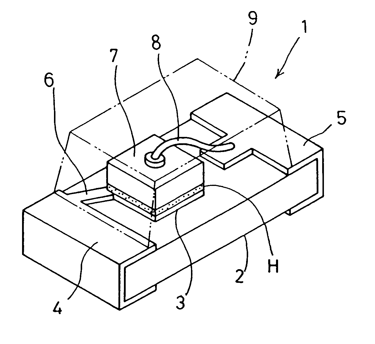
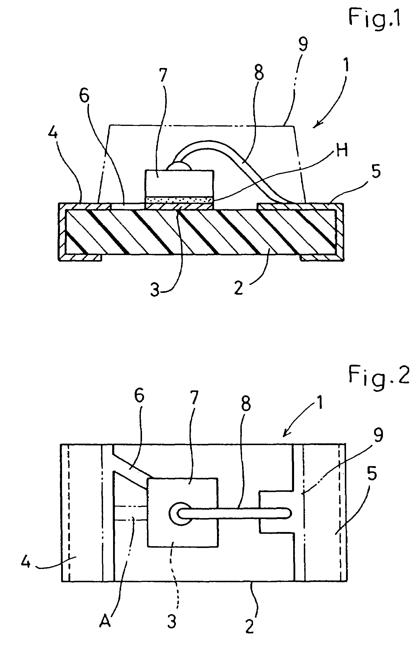
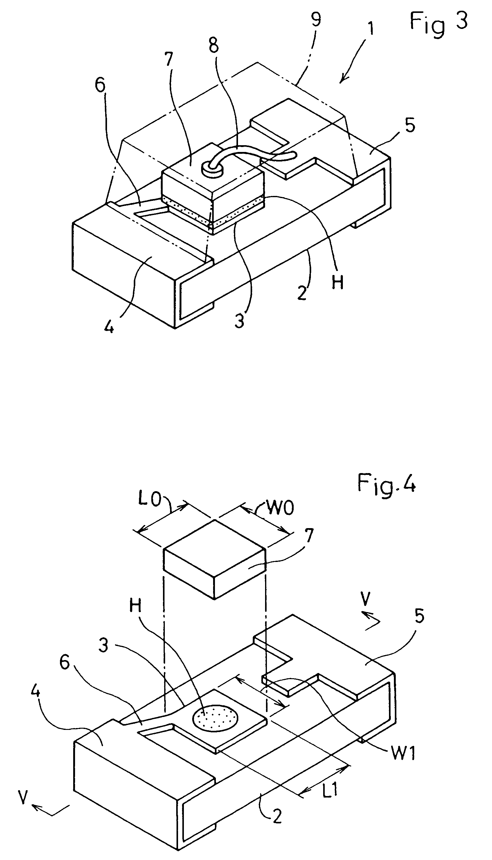
[0060]FIGS. 1-7 show the present invention.
[0061]Indicated by the reference sign 1 in these figures is a chip-type LED device as an embodiment of semiconductor device.
[0062]The chip-type LED device 1 includes an insulating substrate 2 in the form of a chip. The insulating substrate 2 has an upper surface formed with a rectangular die pad 3 and a pair of terminal electrodes 4, 5 all of which are made of a metal film, and a narrow patterned conductor 6 made of a metal film and electrically connecting the terminal electrode 4 to the die pad 3.
[0063]The chip-type LED device 1 further includes an LED chip 7 bonded to the upper surface of the die pad 3, a thin metal wire 8 connecting the LED chip 7 and the terminal electrode 5 by wire bonding, and a molded portion 9 made of a light-permeable synthetic resin such as a transparent resin for packaging the LED chip 6 and the wiring pattern 6.
[0064]The paired terminal electrodes 4, 5 extend from the upper surface onto an end surface and a lowe...
second embodiment
[0080]FIGS. 13-19 show the present invention.
[0081]Indicated by the reference sign 11 in these figures is a chip-type LED device. The chip-type LED device 11 includes an insulating substrate 12 in the form of a chip. The insulating substrate 12 has an upper surface formed with a die pad 13 made of a metal film to have a circular configuration with a diameter D, and a pair of terminal electrodes 14 and 15 made of a metal film and provided on opposite sides of the die pad. The upper surface of the insulating substrate 12 is further formed with a narrow patterned conductor 16 made of a metal film and electrically connecting the terminal electrode 14 to the die pad 13.
[0082]The chip-type LED device 11 further includes an LED chip 17 bonded to the upper surface of the die pad 13, a thin metal wire 18 connecting an electrode on the upper surface of the LED chip 17 to the terminal electrode 15 by wire bonding, and a molded portion 19 made of a light-permeable synthetic resin such as a tran...
third embodiment
[0098]FIGS. 21 and 22 show the present invention.
[0099]In the chip-type LED device 21 according to the third embodiment, instead of the paired electrode terminals and the die pad all of which comprise a metal film formed on an insulating substrate, a pair of electrode terminals and a die pad all of which comprise a relatively thick metal plate are provided, and the insulating substrate is not used.
[0100]Specifically, both of the electrode terminal 25 and the electrode terminal 24 connected to the circular die pad 23 via a narrow patterned conductor 26 are made of a metal plate. Similarly to the foregoing embodiments, an LED chip 27 is bonded on the upper surface of the die pad 23 with solder paste H, and an electrode on the LED chip 27 is connected to the electrode terminal 25 by wire bonding using a metal wire 28. The LED chip 27, the narrow patterned conductor 26 and the metal wire 28 are packaged with a molded portion 29 made of a light-permeable synthetic resin such as a transpa...
PUM
 Abstract
Description
Claims
Application Information
 - R&D
- Intellectual Property
- Life Sciences
- Materials
- Tech Scout
- Unparalleled Data Quality
- Higher Quality Content
- 60% Fewer Hallucinations
Browse by: Latest US Patents, China's latest patents, Technical Efficacy Thesaurus, Application Domain, Technology Topic, Popular Technical Reports.
© 2025 PatSnap. All rights reserved.Legal|Privacy policy|Modern Slavery Act Transparency Statement|Sitemap|About US| Contact US: help@patsnap.com


