Current sharing scheme for multiple CCF lamp operation

a current balancing and lamp technology, applied in the direction of circuit arrangement, fixed transformers, inductance, etc., can solve the problems of reduced electronic control and power switching devices, system cost, and difficulty in achieving equal current sharing among lamps

a current balancing and lamp technology, applied in the direction of circuit arrangement, fixed transformers, inductance, etc., can solve the problems of reduced electronic control and power switching devices, system cost, and difficulty in achieving equal current sharing among lamps

US7242147B2Inactive Publication Date: 2007-07-10MICROSEMI CORP

Image

  • Current sharing scheme for multiple CCF lamp operation
  • Current sharing scheme for multiple CCF lamp operation
  • Current sharing scheme for multiple CCF lamp operation

Examples


Embodiment Construction

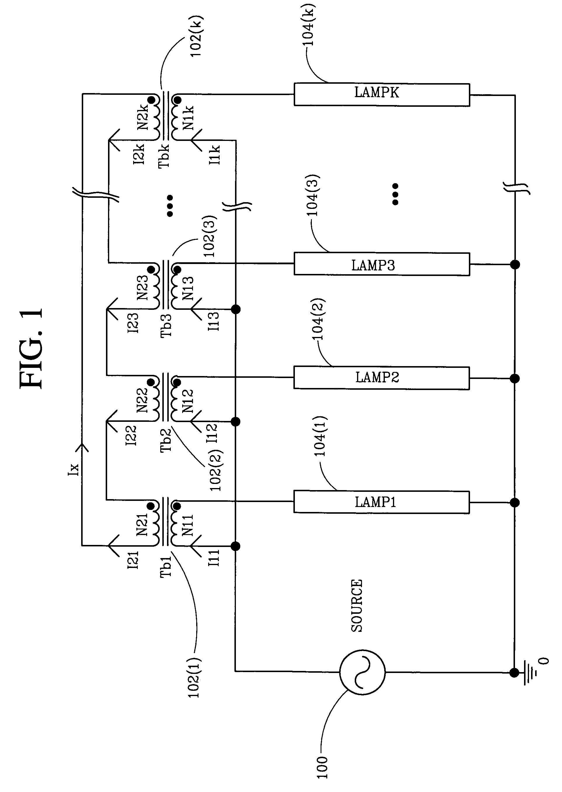
[0031]Embodiments of the present invention will be described hereinafter with reference to the drawings. FIG. 1 is a schematic diagram of one embodiment of a backlight system with a ring balancer coupled between an input AC source 100 and high voltage terminals of multiple lamps (LAMP1, LAMP2, . . . LAMPK) shown as lamps 104(1)โ€“104(k) (collectively the lamps 104). In one embodiment, the ring balancer comprises multiple balancing transformers (Tb1, Tb2, . . . Tbk) shown as balancing transformers 102(1)โ€“102(k) (collectively the balancing transformers 102). Each of the balancing transformers 102 is designated for a different one of the lamps 104.

[0032]The balancing transformers 102 have respective primary windings coupled in series with their designated lamps 104. The balancing transformers 102 have respective secondary windings connected in series with each other and in phase to form a short circuit (or closed) loop. The polarity of the secondary windings is aligned so that the voltag...


PUM

PropertyMeasurementUnit
voltageaaaaaaaaaa
currentsaaaaaaaaaa
voltageaaaaaaaaaa

Abstract

A ring balancer comprising a plurality of balancing transformers facilitates current sharing in a multi-lamp backlight system. The balancing transformers have respective primary windings separately coupled in series with designated lamps and have respective secondary windings coupled together in a closed loop. The secondary windings conduct a common current and the respective primary windings conduct proportional currents to balance currents among the lamps. The ring balancer facilitates automatic lamp striking and the lamps can be advantageously driven by a common voltage source.

Description

CLAIM FOR PRIORITY[0001]This application claims the benefit of priority under 35 U.S.C. ยง 119(e) of U.S. Provisional Application No. 60 / 508,932, filed on Oct. 6, 2003, and entitled A CURRENT SHARING SCHEME AND SHARING DEVICES FOR MULTIPLE CCF LAMP OPERATION, the entirety of which is incorporated herein by reference.BACKGROUND OF THE INVENTION[0002]1. Field of the Invention[0003]The present invention relates generally to balancing transformers and more particularly to a ring balancer used for current sharing in a multi-lamp backlight system.[0004]2. Description of the Related Art[0005]In liquid crystal display (LCD) applications backlight is needed to illuminate the screen to make a visible display. With the increasing size of LCD display panels (e.g., LCD television or large screen LCD monitor), cold cathode fluorescent lamp (CCFL) backlight systems may operate with multiple lamps to obtain high quality illumination for the display. One of the challenges to a multiple lamp operation...

Claims


Application Information

Patent Timeline
10 Jul 2007
Publication
US7242147B2
IPC
H05B37/00; H02M5/45; H01F; H05B37/02; H05B39/00; H05B41/16; H05B41/24; H05B41/282
CPC
H01F38/00; H05B41/245; H05B41/2822; H01F30/12; H05B41/24; H05B41/16; H05B39/00
Inventors
JIN, XIAOPING