Optical system using total internal reflection images

an optical system and total internal reflection technology, applied in the field of optical systems using total internal reflection images, can solve the problem of undesirable reflections from the outside surface of the lens

Active Publication Date: 2007-07-10
GOOGLE LLC
View PDF11 Cites 175 Cited by
  • Summary
  • Abstract
  • Description
  • Claims
  • Application Information

AI Technical Summary

Benefits of technology

[0005]A collimating system between the illumination element and the display element includes a condensing lens element and an aperture located at a focal length of the condensing lens element. In one embodiment, the aperture and the light source are

Problems solved by technology

Referring to FIG. 1 herein, the light is directed axially, and

Method used


Image

  • Optical system using total internal reflection images
  • Optical system using total internal reflection images
  • Optical system using total internal reflection images

Examples


Embodiment Construction

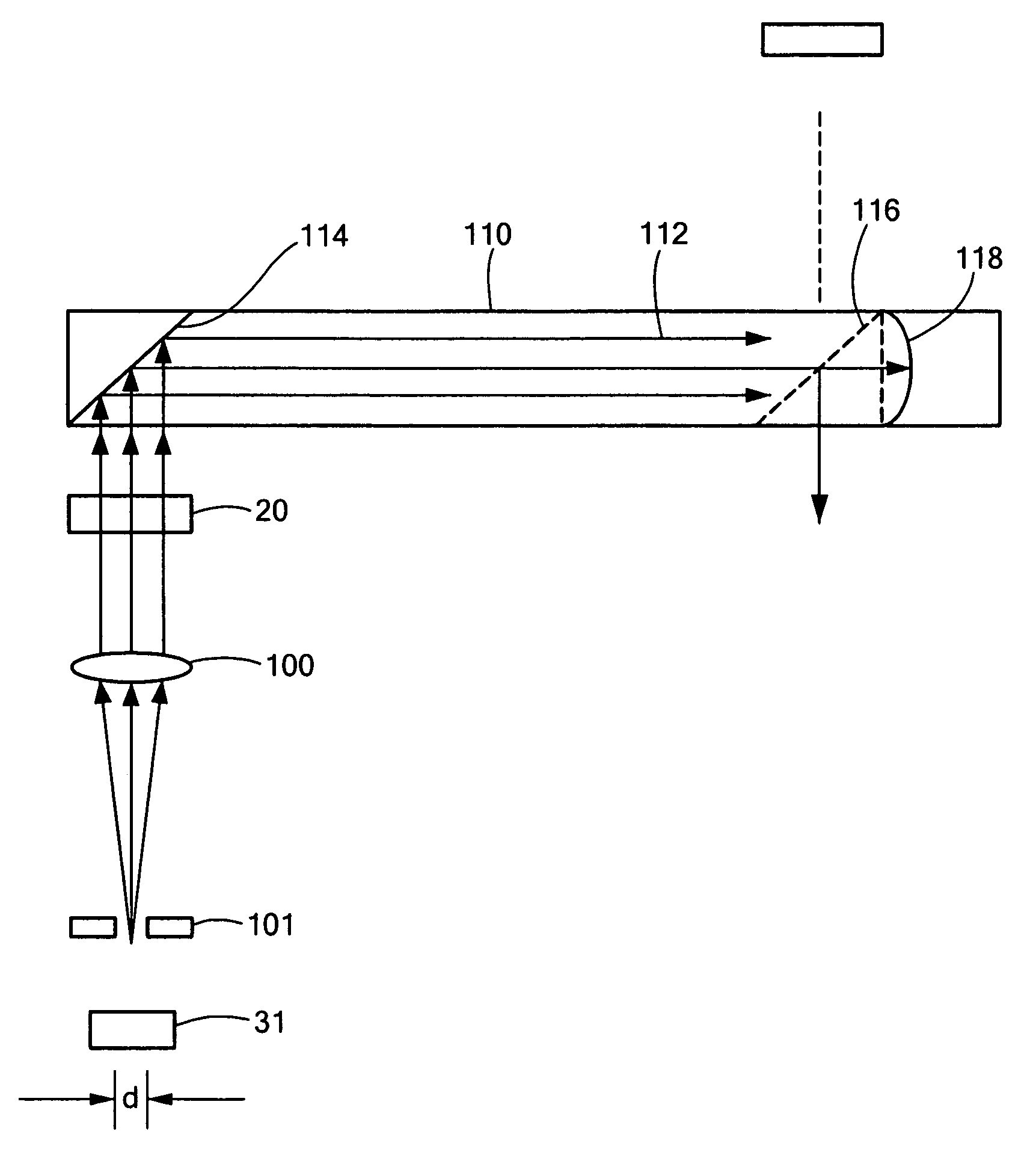
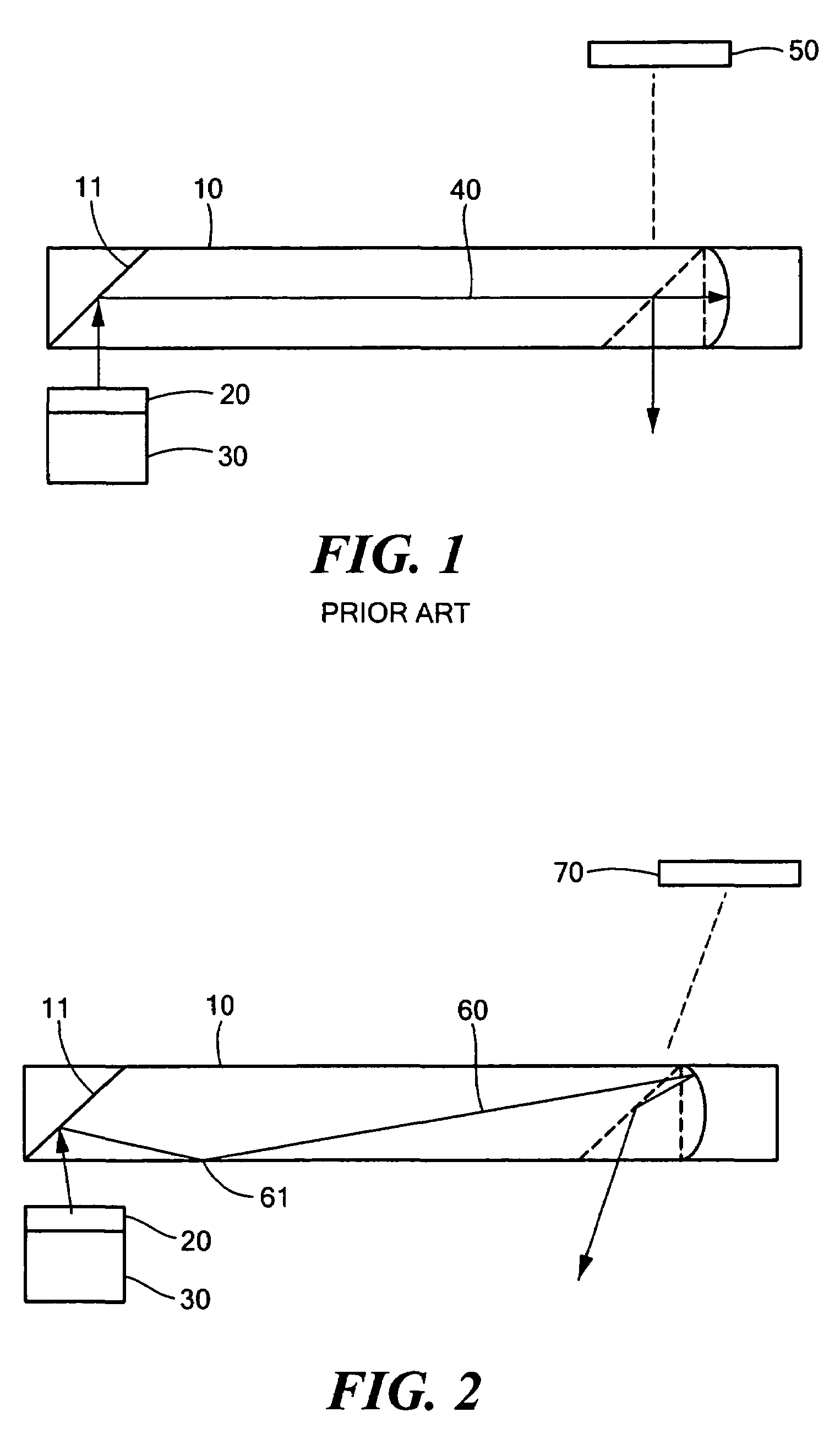
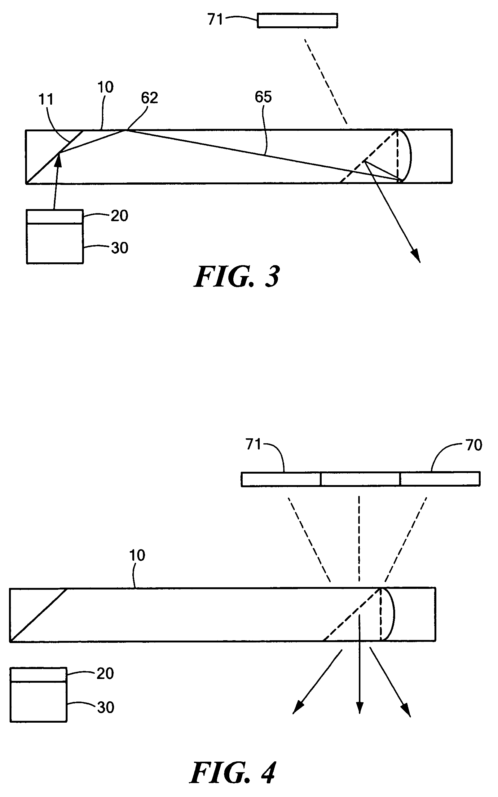
[0017]It is the object of this invention to control the propagation of the light through the lens and to make possible or eliminate total internal reflection (TIR) from the lens surface. This control is attained through design of the back light system used to illuminate the LCD.

[0018]We can consider the lens or plate to be a waveguide in which a number of modes can propagate, including the axial mode which does not require any reflection from the waveguide surface. (This is in analogy to a multi-mode optical fiber in which rays can propagate axially or by using reflection at the interface between the fiber core and the cladding.) To control the mode of propagation through the waveguide, it is only necessary to control the light rays incident on the LCD. Rays which are well collimated parallel or at small changes to the optical axis will propagate axially, and rays that pass at larger angles through the LCD may be reflected. The present method allows the modes of the waveguide to be ...


PUM


Abstract

An optical system for a head mounted display includes a light pipe having two parallel surfaces along which modes can travel by total internal reflection. An illumination element allows selection of modes so that the desired modes can be transmitted along the light pipe, either axially or by total internal reflection.

Description

CROSS REFERENCE TO RELATED APPLICATIONS[0001]This application claims the benefit under 35 U.S.C. § 119(e) of U.S. Provisional Patent application No. 60 / 664,254, filed on Mar. 22, 2005, the disclosure of which is incorporated by reference herein.STATEMENT REGARDING FEDERALLY SPONSORED RESEARCH OR DEVELOPMENT[0002]This invention was made under U.S. Army Aviation and Missile Command Contract No. N31P4Q-04-C-R280. The government has certain rights to this invention.BACKGROUND OF THE INVENTION[0003]The propagation of an image through an eyeglass lens or face mask optical plate is known. See, for example, U.S. Pat. No. 5,886,822. Referring to FIG. 1 herein, the light is directed axially, and reflections from the outside surfaces lens are not desirable. Another known embodiment discusses the use of total internal reflection from the surface of the lens or plate in order to reduce the thickness of the lens, or to increase the field of view. See, for example, U.S. Pat. No. 6,384,982.SUMMARY ...

Claims


Application Information

Patent Timeline
IPC IPC(8): G02B27/14G02B27/30G09G5/00
CPCG02B27/0172G02B6/00G02B2027/0123G02B27/142
Inventor SPITZER, MARK B.RENSING, NOA M.ZAVRACKY, PAUL M.
Owner GOOGLE LLC
Why Eureka
Try Eureka