
Method and system for advanced edge-adaptive interpolation for interlace-to-progressive conversion

a technology of adaptive interpolation and advanced edge, applied in image processing hardware, image enhancement, image analysis, etc., can solve problems such as edge flicker, line flicker and line crawling, and image objects with diagonal edges, so as to reduce computation, improve edge detection precision, and remove possible noise

Inactive Publication Date: 2007-07-10
ENTROPIC COMM INC
View PDF17 Cites 39 Cited by
  • Summary
  • Abstract
  • Description
  • Claims
  • Application Information

AI Technical Summary

Benefits of technology

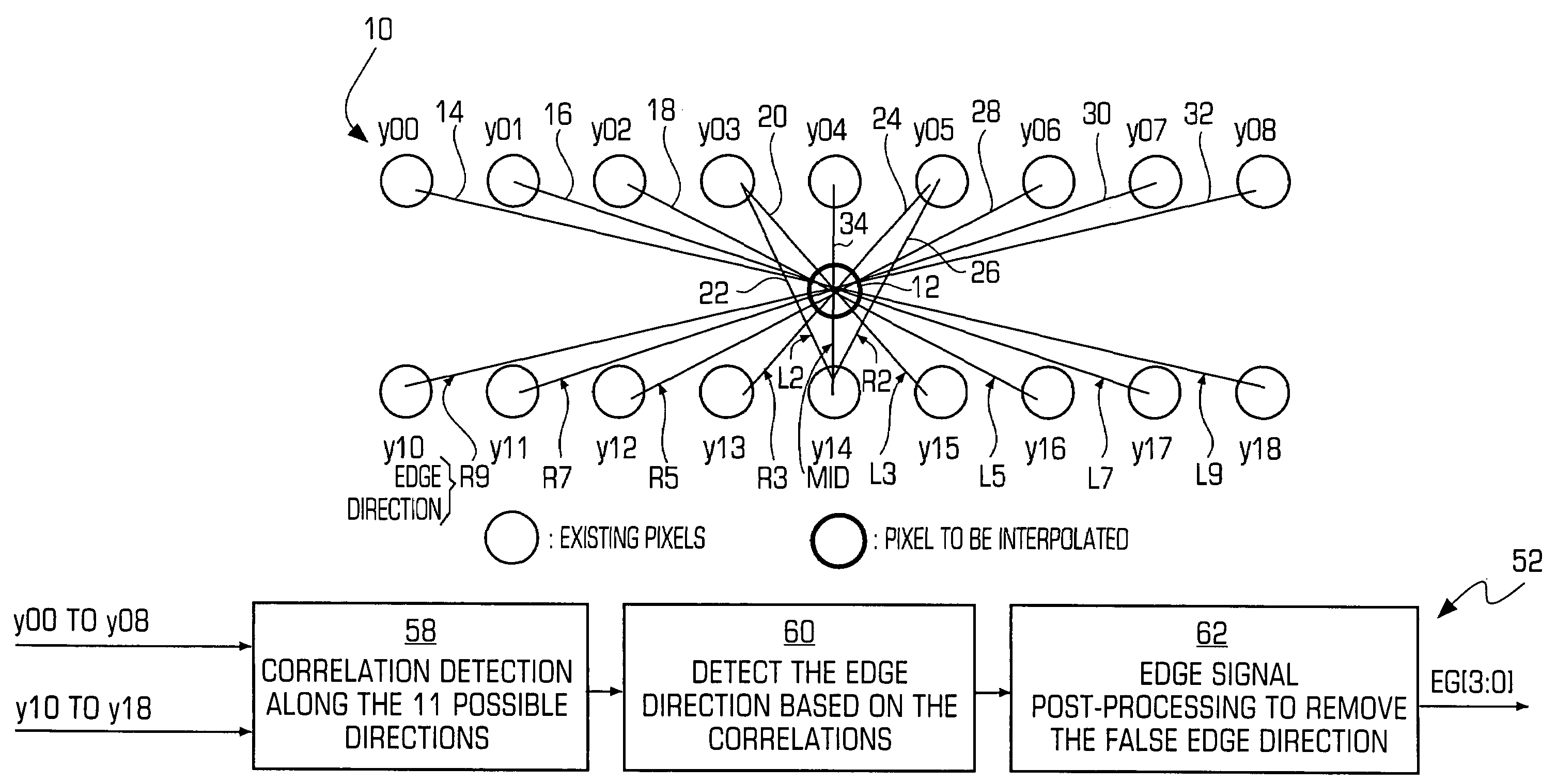
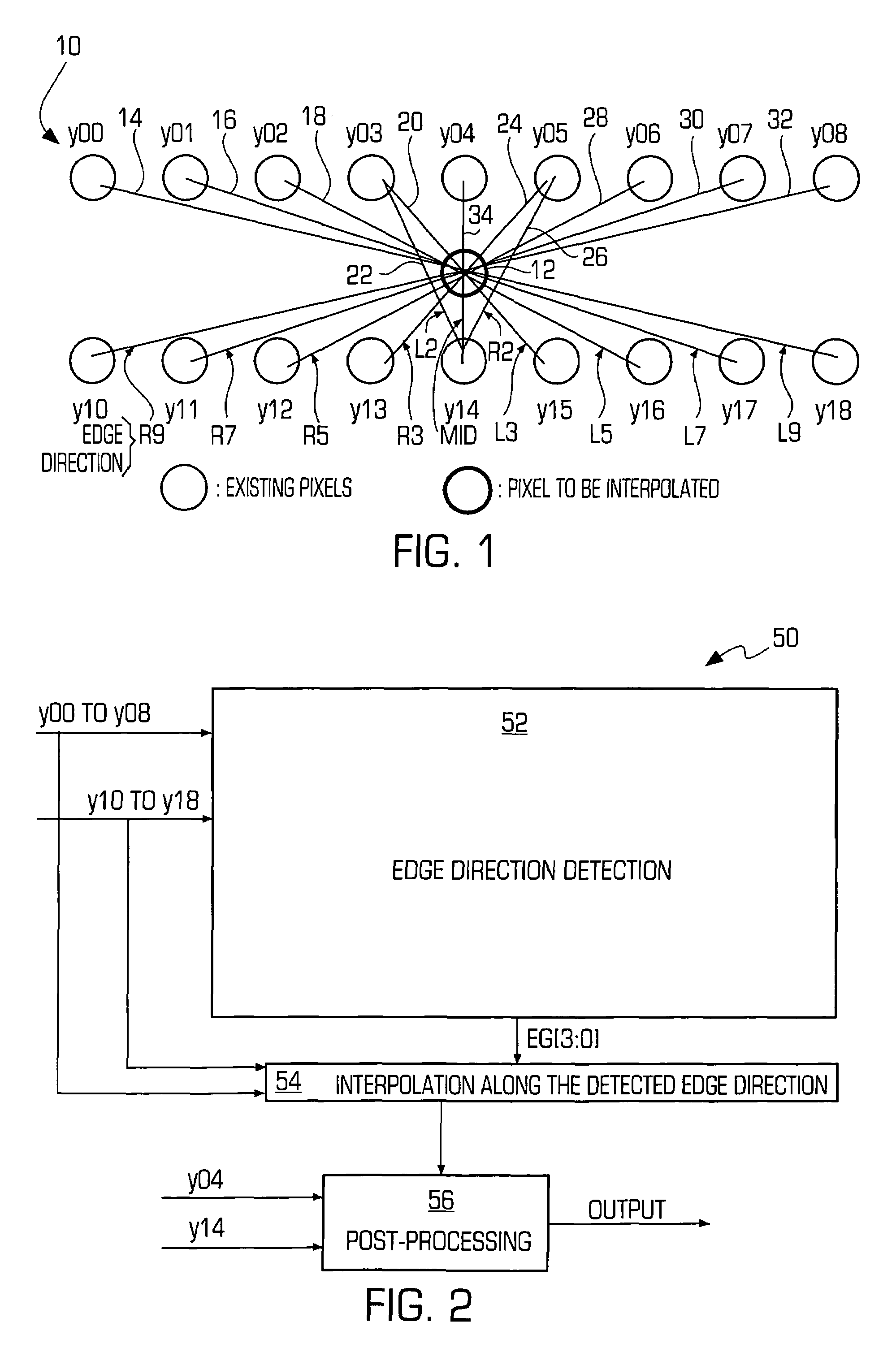
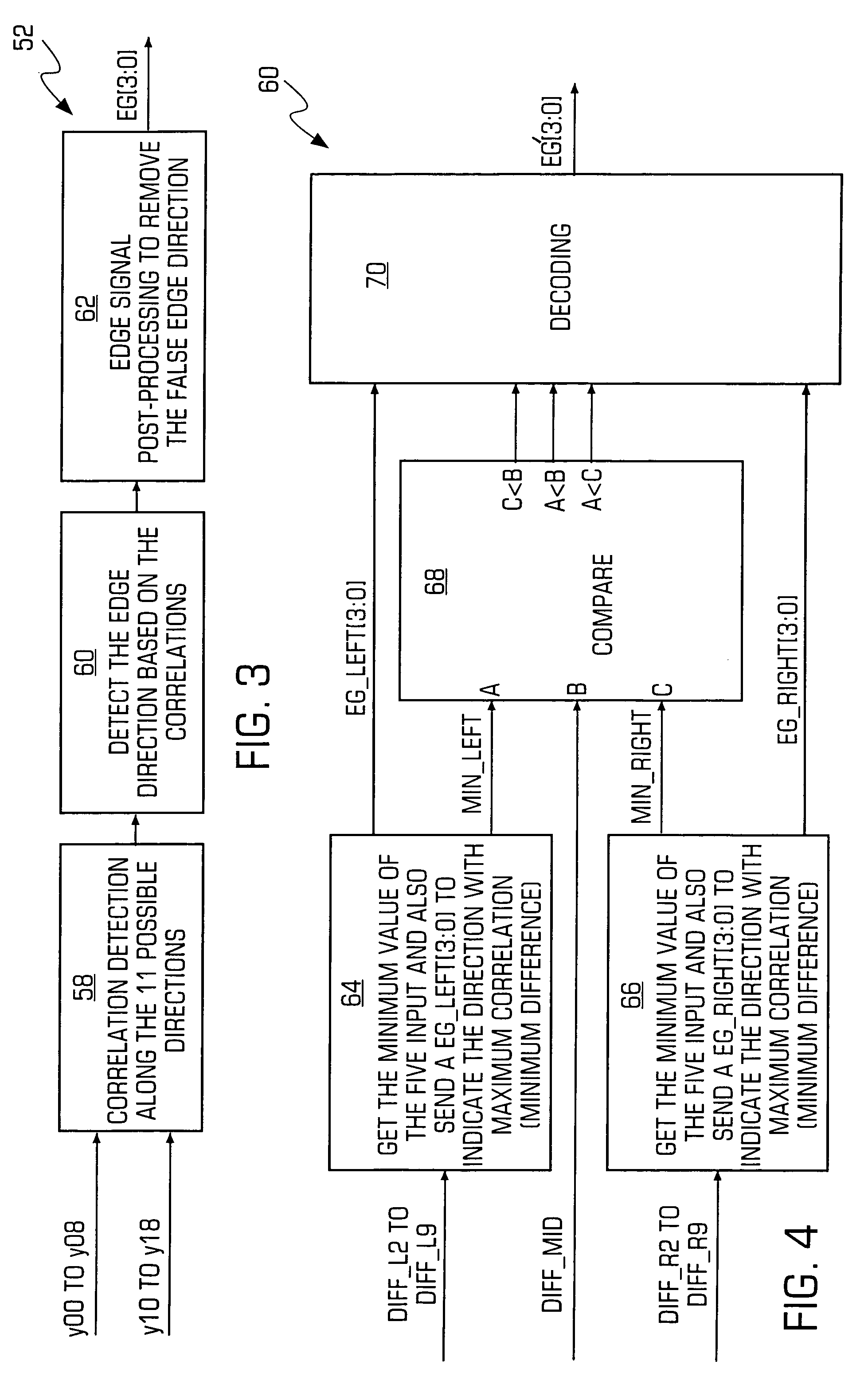
[0009]The present invention provides an improved method and system for edge adaptive interpolation. In one embodiment, the method uses a “9×2” window to detect the edge direction with post-processing to remove any artifacts due to possible false edge detection. A hierarchical scheme may also be employed to reduce the computation required. First, the method detects if there is edge existing along the current pixel. If there is no edge, then the edge detection output will be 90 degrees (the interpolation will be performed along the vertical direction). If an edge does exist, the method determines whether the edge direction is between 0 and 90 degrees, or between 90 and 180 degrees. Once the edge direction is assigned to a particular group (e.g., 0–90 degrees or 90–180 degrees), the edge direction will be detected among five (5) possible directions. The above edge detection process provides an initial edge direction determination. To further improve the edge detection precision, and also to remove the possibility of false edge direction detection, a post-processing technique is applied to the edge direction signal. After the edge signal post-processing, the edge direction information is then passed to the edge adaptive interpolation block to perform interpolation along the edge direction detected. Still another post-processing technique may be applied to the edge adaptive interpolated signal to further remove the possible noise due to an incorrect edge direction detection.
[0010]According to one aspect of the present invention, a method of edge adaptive interpolation for improving the resolution of a pixilated image. The method includes the steps of: receiving data for a first group of pixels and a second group of pixels; determining whether an edge within the image passes through a first pixel located between the first and second group of pixels and whether the edge extends in a first set of directions or a second set of directions to identify a selected set of directions, wherein the determining includes calculating correlation values for each of the directions in the first and second sets; determining a direction signal from the selected set of directions by selecting a minimum correlation value for the selected set of directions; performing a post-processing procedure on the selected direction signal to substantially remove possible error; and determining a luminance value for the first pixel in response to the selected direction.
[0011]According to another aspect of the present invention, a system is provided for improving the resolution of a pixilated image. The system includes a first portion for receiving data for a first group of pixels and a second group of pixels. A second portion determines whether an edge within the image passes through a first pixel located between the first and second group of pixels and whether the edge extends in a first set of directions or a second set of directions to identify a selected set of directions. The second portion is adapted to make the determination by calculating correlation values for each of the directions in the first and second sets. A third portion determines a direction signal from the selected set of directions by selecting a minimum correlation value for the selected set of directions. A fourth portion performs a post-processing procedure on the selected direction signal to substantially remove possible error. The system also includes a fifth portion that determines a luminance value for the first pixel in response to the selected direction.

Problems solved by technology

There many disadvantages to this type of interlace system, such as edge flicker, line flicker and line crawling.
Furthermore, as the demand of using large screen displays increases, these problems have become more critical.
However, jagged edges may result for image objects having diagonal edges.
Jagged edges resulting from interpolation are a visually annoying defect, and can sometimes occur to a degree worse than that on an interlaced display.
Additionally, with a larger window size, there exists a greater possibility of false edge direction detection.
As a result, some prior edge adaptive interpolation methods only employ a “3×2” window to minimize the computation power and also the possibility of false detection.
However, even these improved methods perform detection based around a single pixel or point, without efficiently utilizing neighboring information that can increase the accuracy of the detection process.

Method used


Image

  • Method and system for advanced edge-adaptive interpolation for interlace-to-progressive conversion
  • Method and system for advanced edge-adaptive interpolation for interlace-to-progressive conversion
  • Method and system for advanced edge-adaptive interpolation for interlace-to-progressive conversion

Examples


Embodiment Construction

[0027]The present invention will now be described in detail with reference to the drawings, which are provided as illustrative examples of the invention so as to enable those skilled in the art to practice the invention. Notably, the implementation of certain elements of the present invention may be accomplished using software, hardware, firmware or any combination thereof, as would be apparent to those of ordinary skill in the art, and the figures and examples below are not meant to limit the scope of the present invention. Moreover, where certain elements of the present invention can be partially or fully implemented using known components, only those portions of such known components that are necessary for an understanding of the present invention will be described, and detailed descriptions of other portions of such known components will be omitted so as not to obscure the invention. Preferred embodiments of the present invention are illustrated in the Figures, like numerals bei...


PUM


Abstract

An improved method and system for edge adaptive interpolation. The method uses a “9×2” window to detect the edge direction with post-processing to remove any artifacts due to the possible false edge detection, and a hierarchical scheme is employed to reduce the computation required. The method detects if there is edge existing along the current pixel. If there is no edge, then the edge detection output will be 90 degrees (the interpolation will be performed along the vertical direction). If an edge does exist, the method determines whether the edge direction falls within a first or second direction group. Once the edge direction is assigned to a particular group (e.g., 0–90 degrees or 90–180 degrees), the edge direction will be detected among five (5) possible directions. To further improve the edge detection precision, and also to remove the possibility of false edge direction detection, a post-processing technique may be applied to the edge direction signal. After the edge signal post-processing, the edge direction information is then passed to an edge adaptive interpolation block to perform the interpolation along the edge direction detected. Still another post-processing technique may be applied to the edge adaptive interpolated signal to further remove the possible noise due to an incorrect edge direction detection.

Description

FIELD OF THE INVENTION[0001]The present invention generally relates to image processing methods and systems, and more particularly, to a method and system for advanced edge adaptive interpolation for interlace to progressive conversion, which may be used to improve the resolution of pixilated images.BACKGROUND OF THE INVENTION[0002]Interlaced scanning schemes have been widely adopted in current display monitor systems, including television systems. In a typical interlaced system, the sequence of video fields alternates between odd fields (e.g., fields containing odd numbered lines) and even fields (e.g., fields containing even numbered lines). A conventional display monitor receiving the sequence of fields reproduces each video field in the sequence. Each field is displayed on the display screen, such as a television. For example, first an odd field is displayed, using the odd-numbered scan lines, and then an even field is displayed using the even-numbered scan lines, and so on.[000...

Claims


Application Information

Patent Timeline
Patent Type & Authority Patents(United States)
IPC IPC(8): G06K9/32G06K9/40H04N1/46H04N7/01G06T3/40G06T5/00
CPCG06T3/4007G06T3/403G06T5/20G06T7/0085G06T5/002G06T2200/28G06T2207/20032G06T7/13G06T5/70H04N7/01
Inventor JIANG, JIANDE
Owner ENTROPIC COMM INC
Learn More