Method and apparatus for determining hysteresis

a technology of hysteresis and apparatus, applied in the field of process automation systems, can solve problems such as errors in the final calculation of characteristic curves, various kinds of interference,

Inactive Publication Date: 2007-07-10
METSO AUTOMATION OY
View PDF6 Cites 9 Cited by
  • Summary
  • Abstract
  • Description
  • Claims
  • Application Information

AI Technical Summary

Benefits of technology

[0013]The object of the invention is to provide a new method and apparatus for determining hysteresis or backlash of a process device in normal run in a process in a relatively simple and accurate manner.

Problems solved by technology

In addition, various kinds of interference occur.
As the control direction changes, the measured output may fall in a vague area due to hysteresis or backlash and thus cause errors in the final calculation of characteristic curves.

Method used


Image

  • Method and apparatus for determining hysteresis
  • Method and apparatus for determining hysteresis
  • Method and apparatus for determining hysteresis

Examples


example

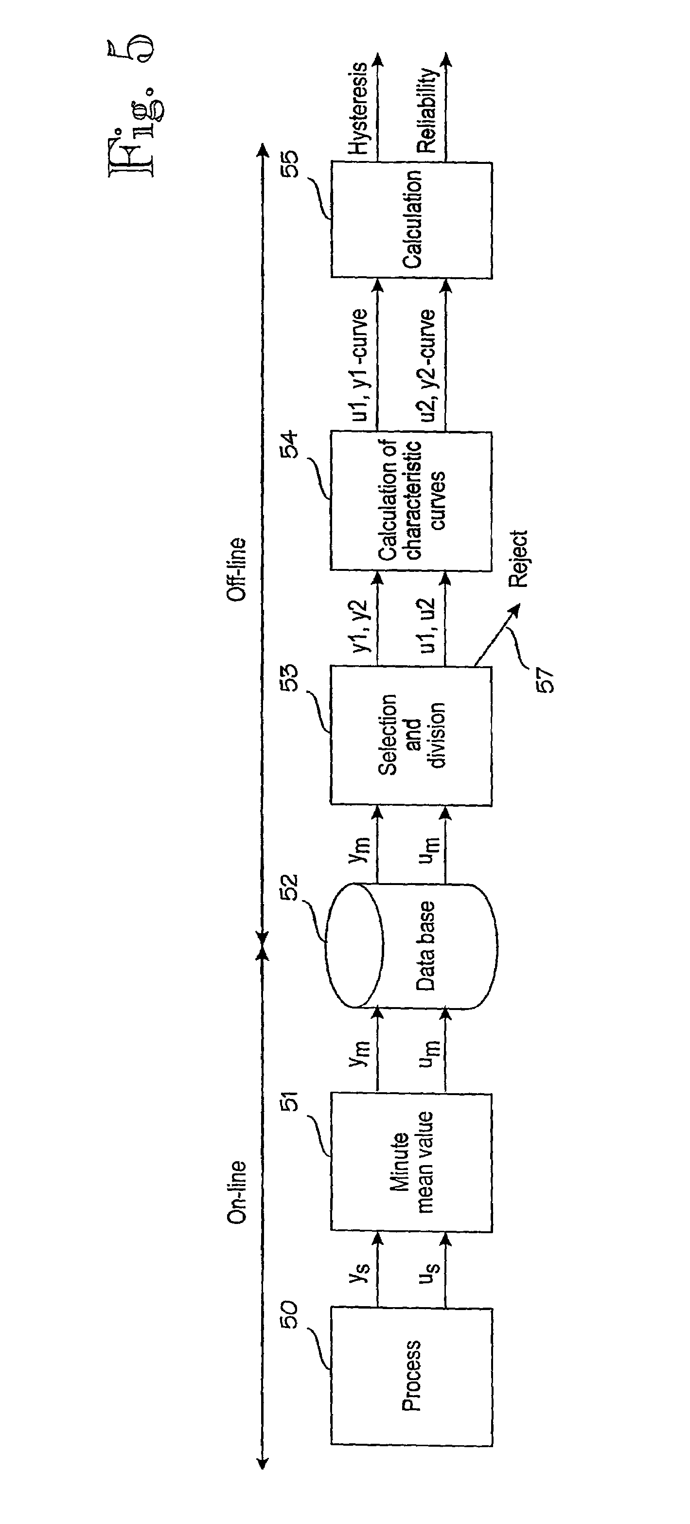
[0075]The calculation of the characteristic curve in the embodiment described above will be described here by an example. For the sake of clarity, the example describes only the calculation of one characteristic curve. In practice, the hysteresis calculation updates two characteristic curves according to the same principle.

[0076]Parameters used in the example[0077]Number of bins: nbin=4[0078]Control min: umin=0[0079]Control max: umax=30[0080]Thus the distance between the bins is ust=10.

[0081]Before updating, the vectors describing the characteristic curve do not actually include any information. The vectors are[0082]Measurements y0 of characteristic curve[0083]Controls u0 of characteristic curve[0084]Frequency information (number of hits) nct on characteristic curve

y0=[0 0 0 0]

u0=[0 10 20 30]

nct=[0 0 0 0]

[0085]The following pair of control and measurement is added to the characteristic curve

um=12

ym=3

First, bins are selected according to the following formula

[0086]b1<um-uminumax-u...


PUM


Abstract

The invention relates to a method and a system for determining hysteresis of a process device in a process environment. The process comprises collecting (50) second-level sample data ys and us from control and measurement signals u and y of a control circuit. Minute mean values y(min) and u(min), which are stored in a database (52), are calculated from these second-level measurement values. The pairs suitable for hysteresis calculation are selected from the minute-level sample pairs um and ym according to a certain procedure. The pairs are also divided into two groups. Unsuitable pairs are rejected (57). Two characteristic curves (54) are calculated from the selected pairs (um, ym) for hysteresis calculation (55). The calculation (55) also includes a routine which evaluates the reliability of the identified hysteresis.

Description

FIELD OF THE INVENTION[0001]The invention relates to process automation systems.BACKGROUND OF THE INVENTION[0002]In a process automation system, a control loop typically consists of a process, a measurement, a controller and an actual control element, such as a valve, and a related device, such as a valve controller (positioner) and an actuator. An optimal process control depends on how appropriately all these components function.[0003]In the processing industry, such as the pulp and paper industry, and petroleum refining, petrochemical and chemical industries, various control valves mounted in the plant pipe system control material flows in the process. A material flow may contain any fluid material, such as flowing subs stances, liquors, fluids, gases or vapours. At its simplest, the control valve may be a manually-controlled mechanical valve. Usually, the valve is provided with a valve controller and an actuator. The valve controller and actuator adjust the position of a control ...

Claims


Application Information

Patent Timeline
Patent Type & Authority Patents(United States)
IPC IPC(8): G06F15/00G05B13/02G05B19/00G05B23/02
CPCG05B19/00
Inventor FRIMAN, MATS
Owner METSO AUTOMATION OY
Why Eureka
Try Eureka