
Mounting stents on stent delivery systems

a stent and stent technology, applied in the field of drugeluting medical devices, can solve the problems of unfavorable stent crimping, unfavorable stent crimping, and insufficient stent crimping, so as to reduce the time required for crimping, reduce labor, and increase yield

Inactive Publication Date: 2014-06-17
ABBOTT CARDIOVASCULAR
View PDF44 Cites 26 Cited by
  • Summary
  • Abstract
  • Description
  • Claims
  • Application Information

AI Technical Summary

Benefits of technology

The invention is a system for crimping stents to balloon catheters. The system includes a crimper head and a pair of stations for positioning the stent and catheter assembly. The crimper head has a computer-controlled system for reducing the labor required to prepare the stent and catheter for crimping. The system automates the process of aligning the stent and catheter, crimping the stent, and monitoring the crimping process. The invention improves efficiency and accuracy in crimping stents, especially polymer stents, which are more sensitive to fracture. The system also reduces the time required for crimping and increases production yields.

Problems solved by technology

Automated, computer-controlled processes replacing manual pre-crimping processes can increase yield, since there is less likelihood that a stent and catheter will be improperly located within the crimper head, which can result in uneven crimping over the length of a stent, or a stent not properly aligned with a balloon markers prior to crimping.
In contrast to a metal stent, a polymer stent must be crimped at a much slower rate due to the inherent limitations of the material compared at that of a metal.
This slower process can produce significant bottlenecks during stent-catheter production.
Inaccurate crimping within the crimper head, e.g., non-uniform applied forces through the crimper jaws when the stent and catheter are not properly located, or positioned within the crimper head, is therefore more likely to cause fracture in polymer stent struts.
This 5-fold increase in crimping time, when multiplied out by the number of polymer stent-balloon assemblies crimped during a production run, poses unique challenges in planning and resource allocation, which is contrast to the time and resource allocation needed for crimping metal stents.

Method used


Image

  • Mounting stents on stent delivery systems
  • Mounting stents on stent delivery systems
  • Mounting stents on stent delivery systems

Examples


Embodiment Construction

[0042]Throughout this disclosure, the balloon expandable implant will be called a “stent”, whether the description is referring to an implant made in whole or part of a metal material or a polymeric material such as PLLA. In some instances, the term “scaffold” may be used, which is specifically referring to a biodegradable, polymer implant.

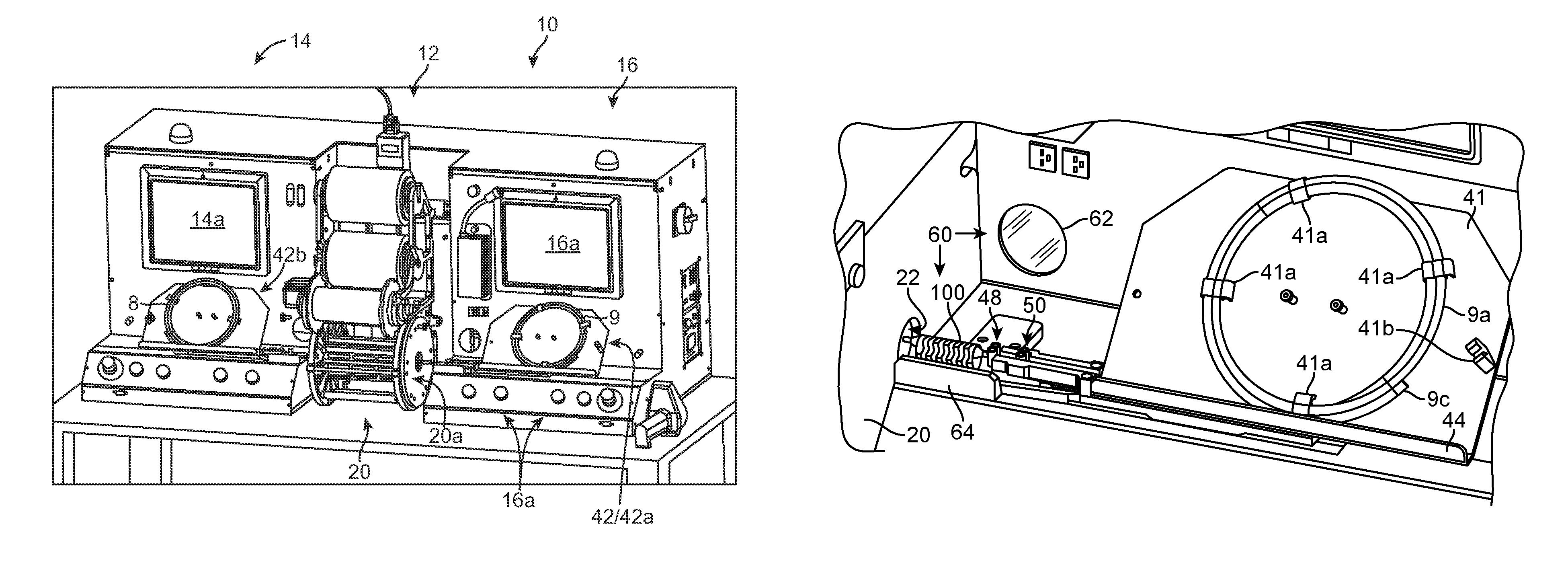
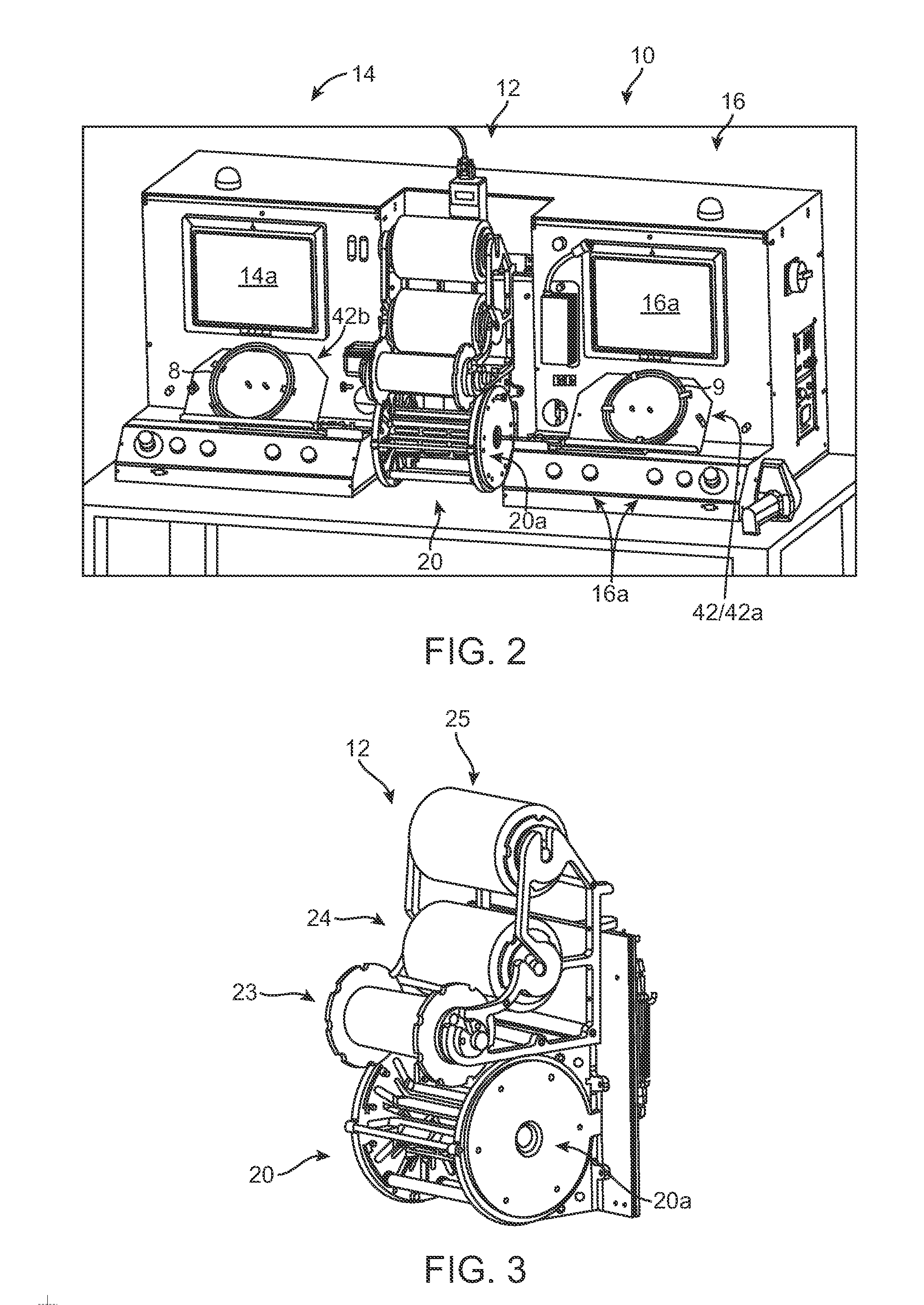
[0043]FIG. 2 illustrates a stent mounting system 10 according to one aspect of the disclosure. The stent mounting system 10 is configured for positioning a stent on a delivery balloon, then crimping the stent to the balloon in an automated fashion. The system 10 is preferably constructed so that two stents may be simultaneously loaded onto separate balloon catheters, then each placed within a crimper head by a computer-controlled positioning and alignment system. Both stents are then crimped to their respective balloon using the same crimper head. As such, two stents may be simultaneously crimped to catheters during a single crimping sequence. The...


PUM

PropertyMeasurementUnit
thicknessaaaaaaaaaa
thicknessaaaaaaaaaa
thicknessaaaaaaaaaa

Abstract

A system for mounting a stent on a balloon catheter includes two positioning and alignment stations, which are used to prepare a stent and catheter for crimping using the same crimping head. The system is configured for automated assembly of the stent and catheter prior to crimping. A catheter and stent are placed on a computer-controlled carriage that delivers the stent and catheter to the crimper head. Before placing the stent and catheter into the crimper head, an automated alignment system locates the stent between balloon markers.

Description

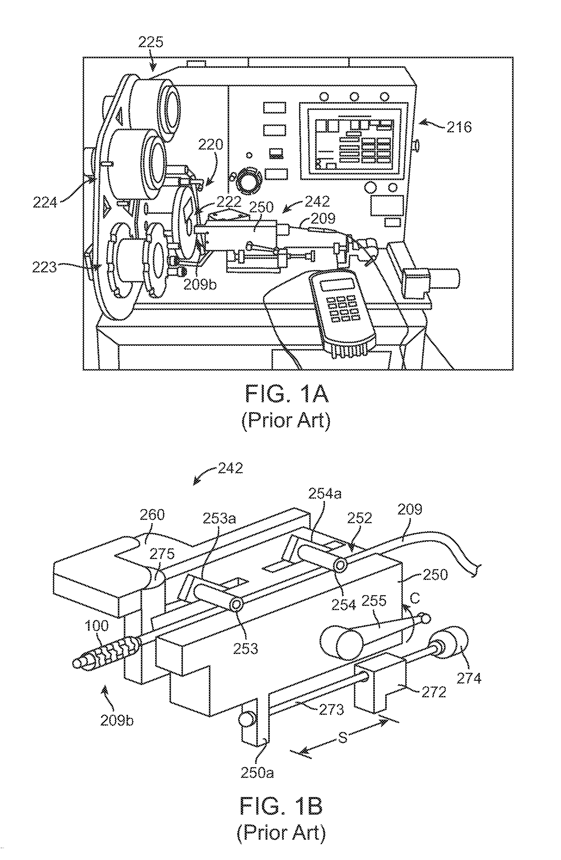
BACKGROUND OF THE INVENTION[0001]1. Field of the Invention[0002]The present invention relates to drug-eluting medical devices; more particularly, this invention relates to systems, apparatus and methods for mounting to a delivery balloon a balloon-expandable stent, such as a polymeric stent.[0003]2. Background of the Invention[0004]FIGS. 1A and 1B depict perspective views of a prior art crimping station used to crimp a balloon expandable stent to a deployment balloon of a balloon catheter. The crimping station includes a crimper head 220, an interactive screen 216 for programming a crimping sequence, e.g., diameter reduction, dwell times between successive crimps, temperature control of the crimper jaws, etc. A carriage 242 aligns a catheter 209 with the opening 222 to the crimper head 220 and advances the distal end 209b of the catheter, where a stent 100 and the balloon are located, into the crimper head 220. The crimper head 220 includes three rollers 223, 224 and 225, which plac...

Claims


Application Information

Patent Timeline
Patent Type & Authority Patents(United States)
IPC IPC(8): B21D39/04
CPCA61F2002/9583A61F2002/9522A61F2/958A61F2/9522A61F2/9524Y10T29/49902Y10T29/53022Y10T29/53065Y10T29/53917Y10T29/53978Y10T29/53987
Inventor VAN, SCIVER, JASON
Owner ABBOTT CARDIOVASCULAR
Learn More