Heat exchanger and temperature control unit

a technology of heat exchangers applied in the field of heat exchanger systems and temperature control units, can solve the problems of increasing the demands of heat exchangers and the temperature control units that utilize them, insufficient heat exchangers that are currently available, and insufficient to meet the needs and goals of current developments and technology, and achieves the effects of maximizing thermal exchange efficiency, long path length, and large surface area

Active Publication Date: 2007-07-17
BE AEROSPACE INCORPORATED
View PDF7 Cites 4 Cited by
  • Summary
  • Abstract
  • Description
  • Claims
  • Application Information

AI Technical Summary

Benefits of technology

[0005]Heat exchanger units in accordance with the invention transport a temperature controlled gas or liquid, or mixture thereof, at substantial velocity in intimate and uninterrupted relation with respect to a moving thermal transfer fluid that is to be used for temperature control, as in a semiconductor fabrication facility. To this end, thermal transfer fluid is directed in a confined but unrestricted helical path at a radius about a central axis, while a variable temperature fluid or gas, such as a refrigerant, is flowed coextensively and continuously in an adjacent helical path in either a parallel or a counter-flow direction. The cross-sectional areas of both flows are small but the fluids may flow at substantial velocities over paths which are arbitrarily long. The heat transfer distances between the fluids in contrast can be very short through the tubing walls, affording high efficiency operation.
[0006]The flow paths are preferably established between two concentric tanks spaced apart by a small distance, within which refrigerant tubing is disposed in a helical geometry about the central axis. Thermal transfer fluid flows in the spaces between the turns of the tubing and the cross-sectional areas of the two flows are small. Thus there is intimate thermal interchange between the two fluids throughout long path lengths and minimal if any thermal losses along the paths. The interior of the tanks provides a volume which may include an impeller for driving thermal transfer fluid and a heater element for energy additive or corrective purposes. Refrigerant flow is driven by pressure from a compressor in a conventional vapor-cycle system but minimal flow impedance is introduced.
[0007]This system may use a liquid refrigerant after compression and condensation, or the refrigerant as a pressurized hot gas after compression but without condensation. Pressurized refrigerant after condensation will be in a liquid / vapor mix in which the temperature is controlled by an expansion valve. Modern molding techniques and assembly techniques can be used in manufacture of the tanks, so the containers can be of low cost materials and precisely reproducible in quantity. Whether cooling or heating, the thermal transfer fluid can regulate temperature efficiently and precisely, and if cooling and heating are both used, a wide temperature range can be established with an electronic controller system.
[0009]Methods in accordance with the invention have a number of different aspects. The long and confined but unrestricted flow of fluid at substantial velocities assures that effective thermal exchange occurs over an adequately long path length and large surface area. This occurs without leakage of fluid or thermal energy between the turns along the flow paths. Thermal energy is transferred over short distances between the two fluid flows, which are of small cross-sectional areas. Assembly of the tanks relative to the helical refrigerant tubing uses the flexibility of the unstressed tubing to position the tubing against the helical ridge on the outside of the inner tank. The refrigerant tubing is also tensioned into firm and precise position between the two tank walls, maximizing thermal exchange efficiency without the need for high precision machining.

Problems solved by technology

The tremendous variety of heat exchangers that is currently available is actually insufficient to satisfy the needs and goals of current developments and technology.
As the art has developed, however, increasing demands have been made on the heat exchangers and the temperature control units that utilize them, in terms of efficiency, size and particularly cost.
Since floor space in such installations is very expensive, the footprint of the temperature control unit should be as small as feasible.

Method used


Image

  • Heat exchanger and temperature control unit
  • Heat exchanger and temperature control unit
  • Heat exchanger and temperature control unit

Examples


Embodiment Construction

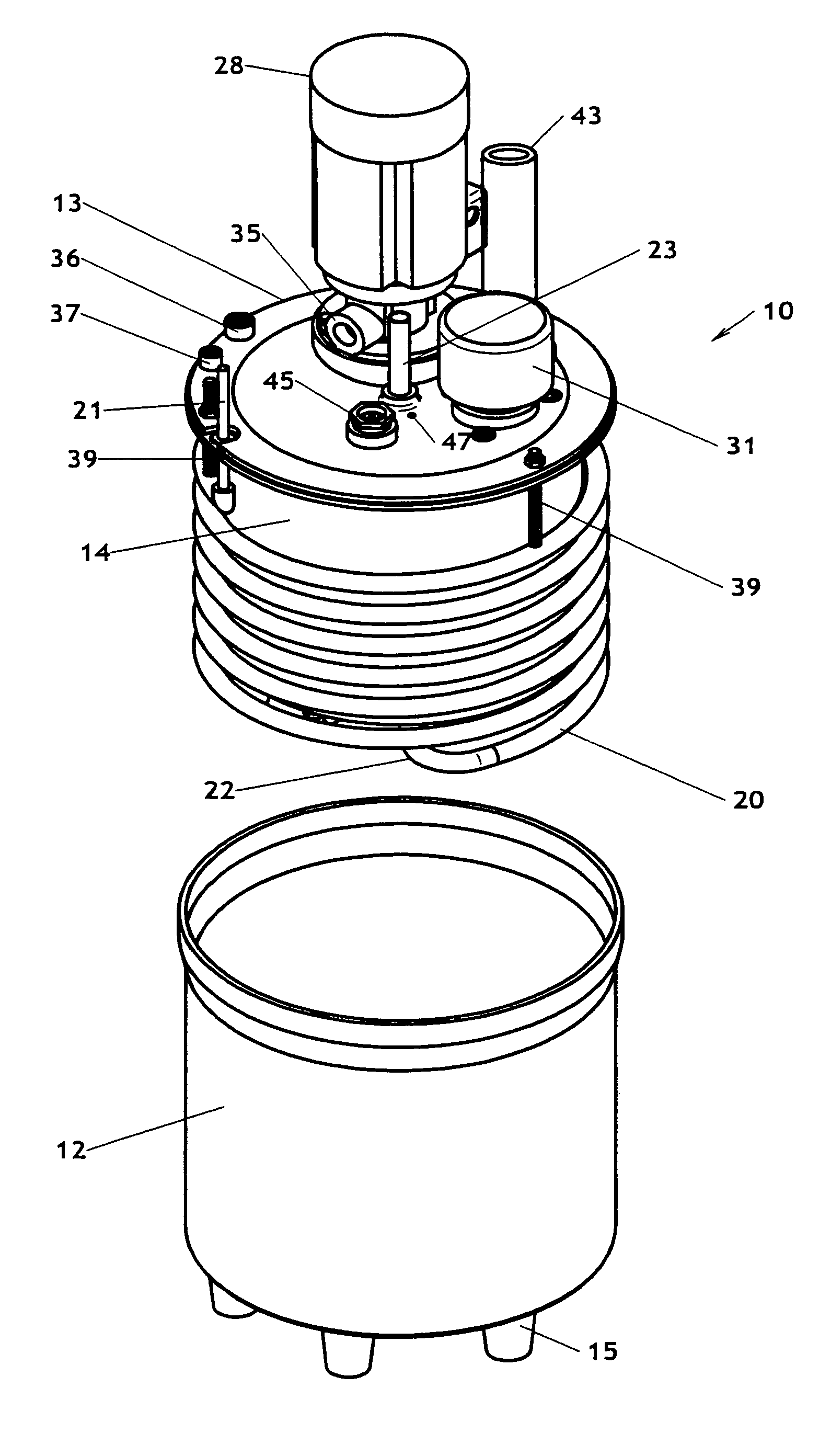
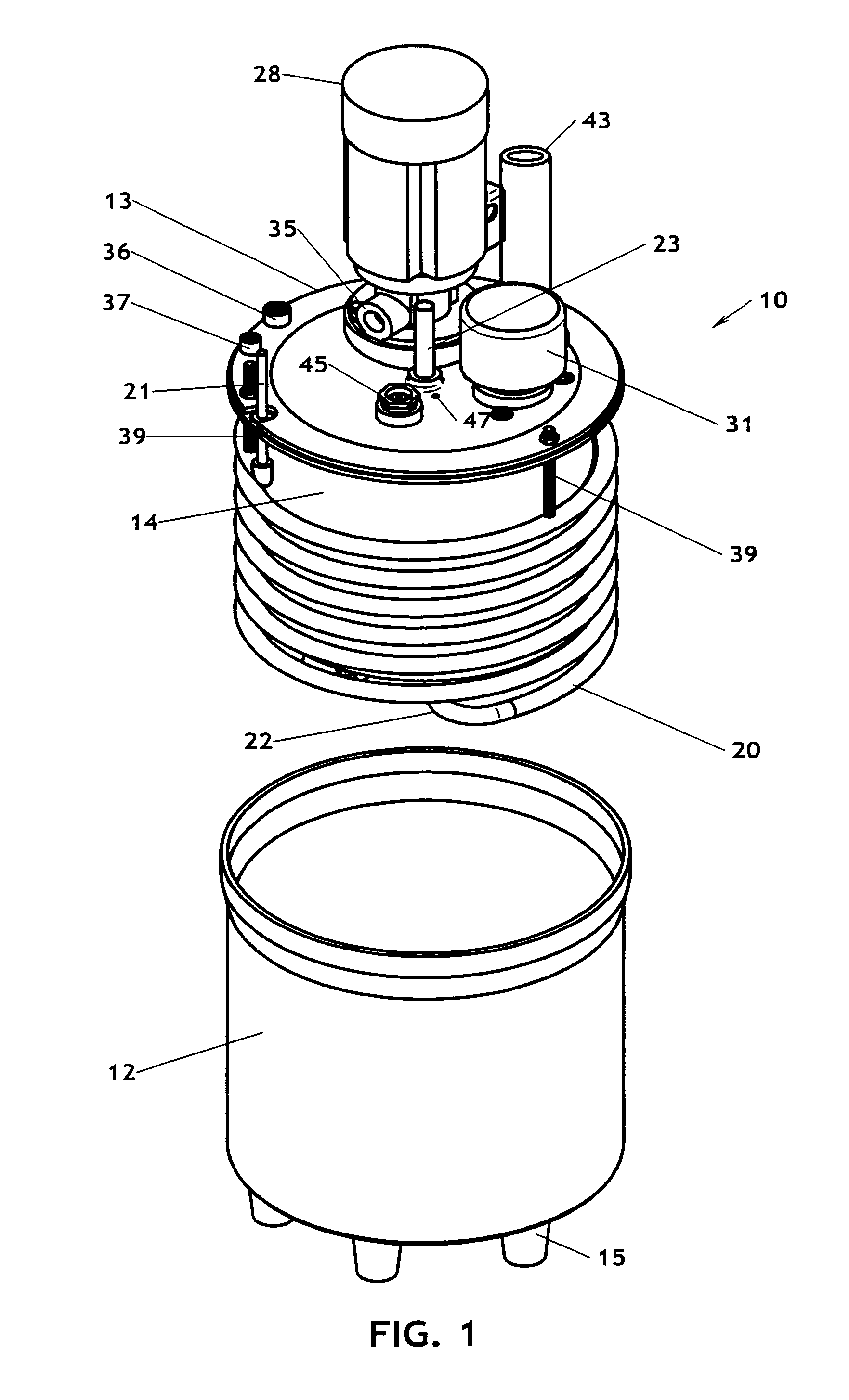
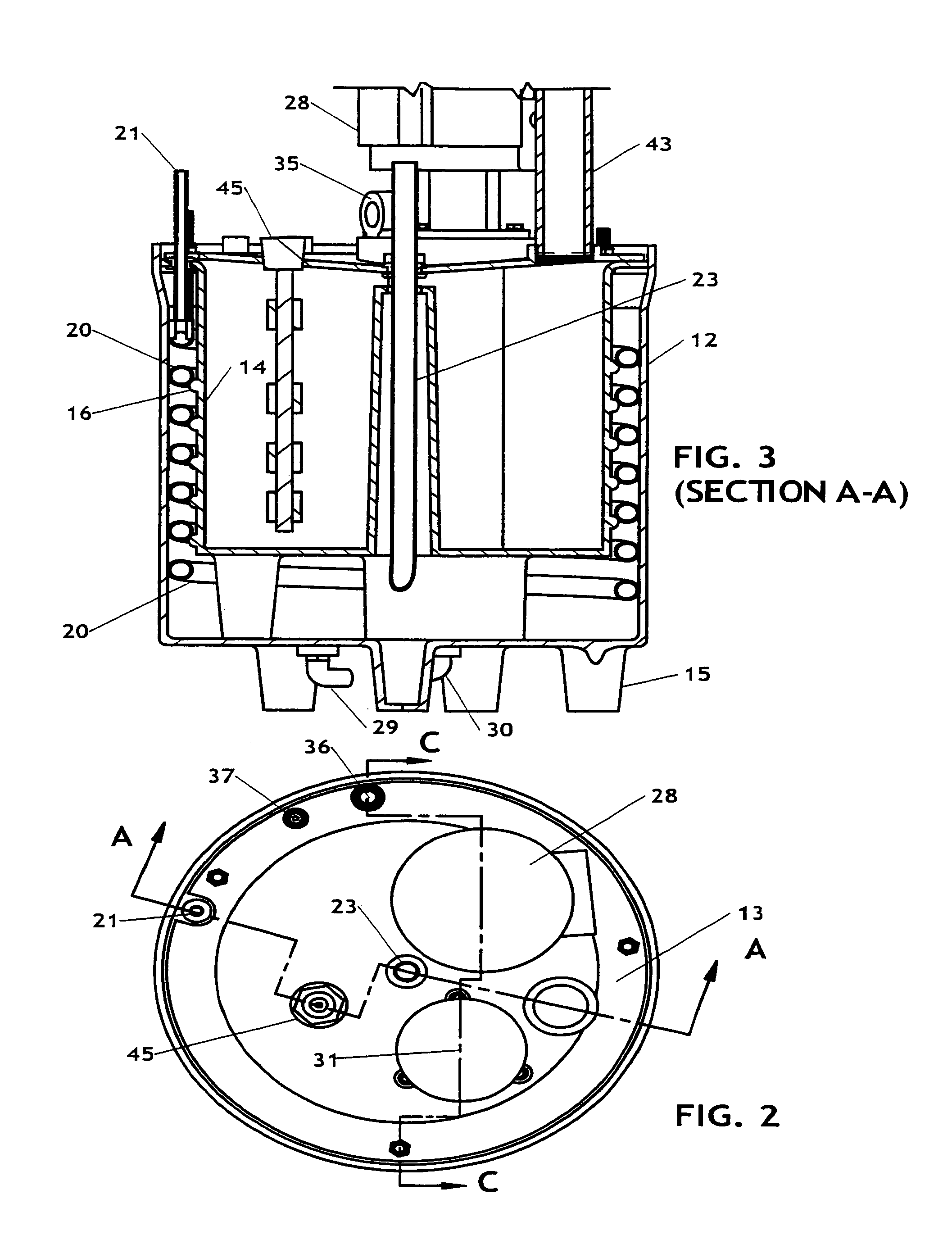
[0022]FIGS. 1-9 are perspective and cross-sectional views of a heat exchanger 10 in accordance with the invention, utilizing a volumetric arrangement including an outer tank 12 of generally cylindrical form. The outer tank 12 has a closed bottom wall and a top edge with a circumferential rim enclosed by a top plate 13. A radial space of predetermined size, established generally by the diametral dimensions of a refrigerant tubing to be inserted between them, is established between the inner wall of the outer tank 12 and the outer wall of an inner tank 14 which is concentric therewith and nested therein. The radial gap is slightly greater than ¾″ in this example. The tanks 12, 14 are generally concentric about a central axis (shown vertical in the Figures), and the unit rests on a number of hollow feet 15 in the bottom walls. The feet 15 may be filled with foam or otherwise internally filled.

[0023]The outer surface of the inner tank 14 includes a helical peripheral ridge 16 that exten...


PUM


Abstract

Systems and methods for heat exchange in accordance with the invention define adequately long-interchange distances for two fluids by wrapping a tube containing a first fluid about the wall of an inner cylindrical tank, within a gap formed with a second concentric tank. A second fluid is transmitted in the space defined between the turns of the tube and the two walls, providing effective short length thermal interchange through the tube walls. The tube is in the line contact with both tank walls and the fluids can flow rapidly over an adequately long length, so that high efficiency is provided in a low cost system.

Description

[0001]This invention relies for priority on a previously filed provisional patent application Ser. No. 60 / 576,706 filed Jun. 2, 2004 by Kenneth W. Cowans, William W. Cowans and Glenn W. Zubillaga.FIELD OF THE INVENTION[0002]This invention relates to heat exchanger systems and to temperature control units which use such systems, with the objective of providing more efficient, compact, economical and versatile heat exchange functions.BACKGROUND OF THE INVENTION[0003]The tremendous variety of heat exchangers that is currently available is actually insufficient to satisfy the needs and goals of current developments and technology. The heat exchangers available include many metal, plastic and other configurations in which thermal energy is transferred between different liquids, between gases and liquids, between liquid / vapor fluids and liquids, and between other combinations of media. Such heat exchangers are used for cooling or heating or both purposes.[0004]As the art has developed, ho...

Claims


Application Information

Patent Timeline
Patent Type & Authority Patents(United States)
IPC IPC(8): F25B41/00F28F1/36F25B27/00F25B49/00F25D31/00F28D1/06F28D7/02F28D7/10G05D23/00
CPCF25D31/002F28D1/06F28D7/022F25B2400/0403F25D31/005F25D2500/02F28D2021/0077
Inventor COWANS, KENNETH W.COWANS, WILLIAM W.ZUBILLAGA, GLENN W.
Owner BE AEROSPACE INCORPORATED
Why Eureka
Try Eureka