Power transmission system of engine

a technology of power transmission system and engine, which is applied in the direction of muscle operated starters, gearing, riding equipment, etc., can solve the problems of difficult riding of vehicles, and achieve the effect of reducing the size of the power transmission system and facilitating riding on or off the vehicl

Inactive Publication Date: 2007-07-17
SUBARU CORP
View PDF25 Cites 23 Cited by
  • Summary
  • Abstract
  • Description
  • Claims
  • Application Information

AI Technical Summary

Benefits of technology

[0005]An object of the present invention is to reduce a power transmission system of an all-terrain vehicle in size in a direction of width of a vehicle.
[0006]Another object of the present invention is to make a rider ride on or off a vehicle easily.
[0009]In the power transmission system of an engine in accordance with the present invention, the crankshaft is arranged parallel to the primary shaft of the continuously variable transmission and the sub-shaft which is arranged parallel to the crankshaft and to which the rotation of the crankshaft is transmitted via the rotary transmission member is arranged concentrically with the primary shaft. Hence, the power transmission system has a three-shaft structure in which the crankshaft, the primary shaft and a secondary shaft are arranged parallel to each other. With this, in a case where the engine is mounted in a lateral direction in the vehicle body, the power transmission system can be reduced in size in a direction of vehicle width. Since the power transmission system mounted under a saddle type seat is reduced in size in a direction of vehicle width, a rider can easily ride on or off the vehicle.

Problems solved by technology

Hence, the arrangement of the power transmission system of the conventional all-terrain vehicle raises a problem that the vehicle is hard to ride.

Method used


Image

  • Power transmission system of engine
  • Power transmission system of engine
  • Power transmission system of engine

Examples


Embodiment Construction

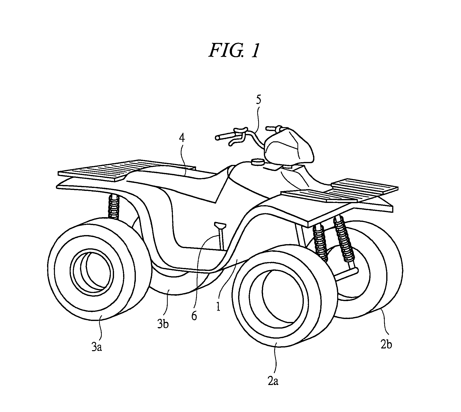
[0015]The preferred embodiment of the present invention will be described in detail with reference to the drawings. FIG. 1 is a perspective view showing one example of a rough terrain vehicle or an all-terrain vehicle (ATV) which is also called a buggy. A vehicle body 1 is provided with front wheels 2a, 2b and rear wheels 3a, 3b and a saddle type seat 4 is provided in the center of the vehicle body 1. A rider sitting on the seat 4 operates a handlebar 5 to drive the vehicle 1.

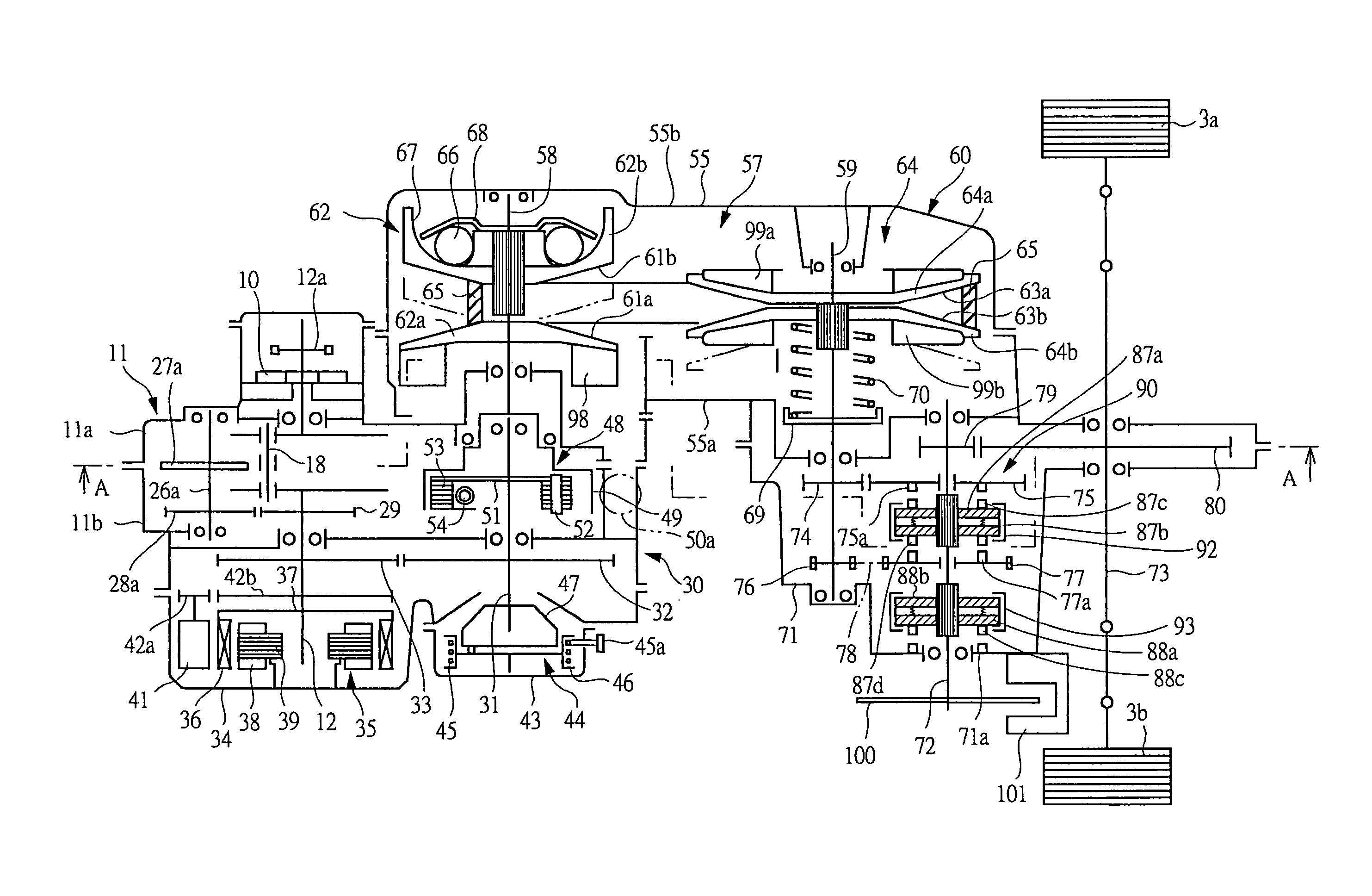
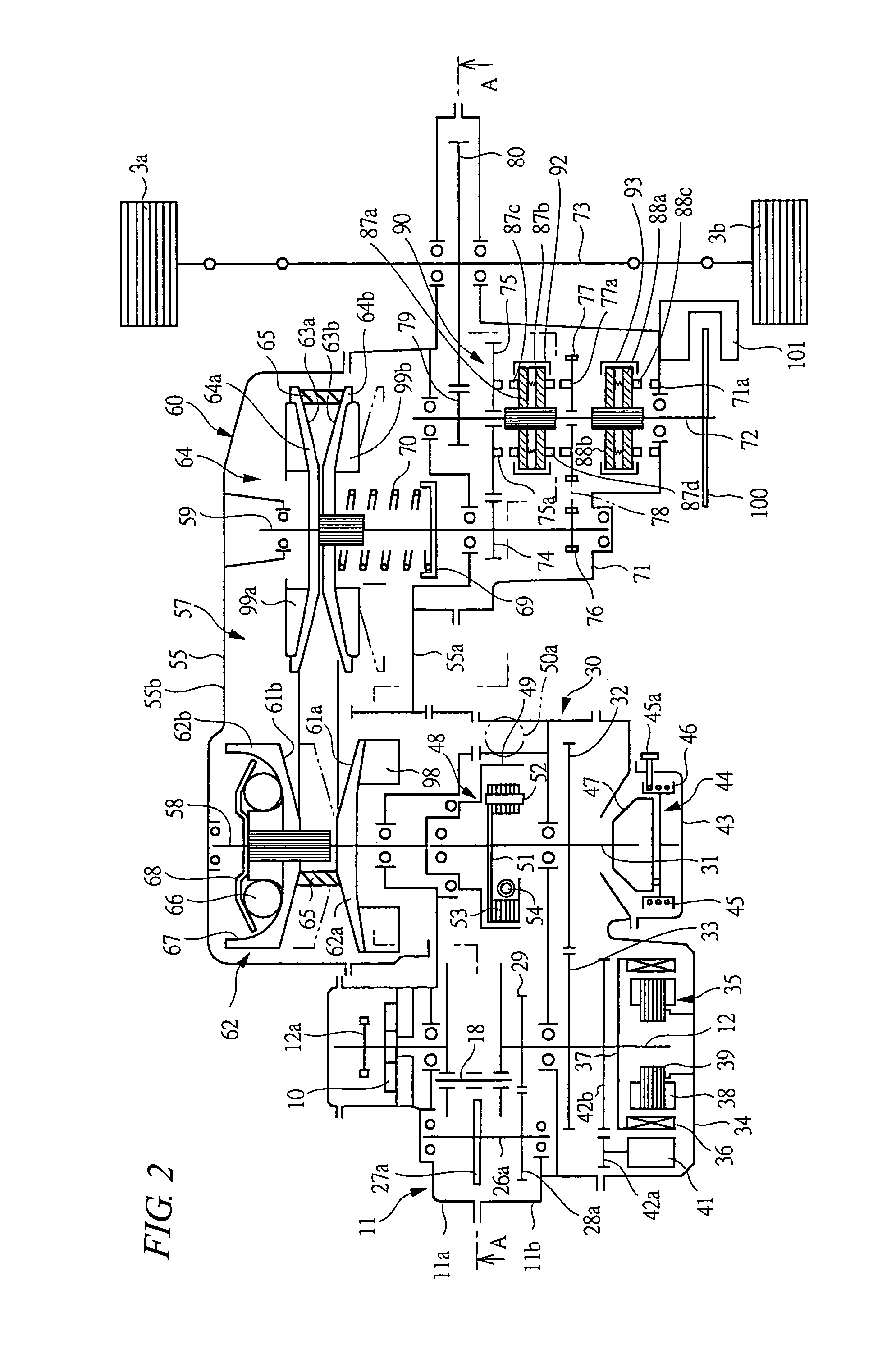
[0016]FIG. 2 is a schematic view showing a power transmission system mounted on the all-terrain vehicle shown in FIG. 1. FIG. 3 is a cross sectional view along a line A-A in FIG. 2. As shown in FIG. 2, a crankshaft 12 is rotatably mounted in a crankcase 11. The crankcase 11 has a case body 11a for supporting one end side of the crankshaft 12 rotatably via a bearing and a case body 11b that supports the other end side of the crankshaft 12 via a bearing and is combined with the case body 11a. The case body 11a is...


PUM


Abstract

The power transmission system of an engine is mounted on the all-terrain vehicle and has a crankshaft driven by the engine and the crankshaft is arranged in a direction of width of a vehicle body. A sub-shaft is arranged parallel to the crankshaft and the rotation of the crankshaft is transmitted to the sub-shaft via gears. A primary shaft is concentrically mounted on the sub-shaft and is provided with a primary pulley having a variable groove width. A secondary pulley coupled to the primary pulley via a V-belt and having a variable groove width. The rotation of the crankshaft is transmitted to the primary shaft via the sub-shaft arranged parallel to the crankshaft.

Description

TECHNICAL FIELD OF THE INVENTION[0001]The present invention relates to a power transmission system of an engine mounted on an all terrain vehicle such as a buggy.BACKGROUND OF THE INVENTION[0002]A rough terrain vehicle or an all-terrain vehicle which is also called a buggy is a four-wheel off-road vehicle for one person and is used as a recreational vehicle for hunting and trail touring and is also used as a practical vehicle for agriculture. In such an all-terrain vehicle, an engine is mounted in a lateral direction in a vehicle body such that a crankshaft extends in a direction of vehicle width and a power transmission system for transmitting engine power to driving wheels is provided with a forward / backward switching mechanism, a belt type continuously variable transmission, a centrifugal clutch and the like (see Japanese Patent Application Laid-open Nos. 10-297294 and 2002-68070)[0003]In a conventional all-terrain vehicle, an engine is mounted in a lateral direction in a vehicle...

Claims


Application Information

Patent Timeline
Patent Type & Authority Patents(United States)
IPC IPC(8): F16H3/08B60K17/02B60K17/06F02N3/02F02N11/00F16H9/14F16H9/18F16H37/02F16H55/56
CPCF16H37/021B60Y2200/20Y10T74/19223
Inventor CHONAN, MITSUGIKOMURO, MASAYUKIMATSUSHIMA, TOSHIYUKI
Owner SUBARU CORP
Why Eureka
Try Eureka