Foundation footing form and accessories

a technology of concrete footings and accessories, applied in the direction of manufacturing tools, auxillary members of forms/shutterings/falseworks, ways, etc., can solve the problems of difficult if not impossible use of wood forms, easy damage to materials commonly used for concrete forms, etc., to achieve convenient storage, easy positioning, and light weight

Inactive Publication Date: 2007-07-17
HUBER DONALD G +1
View PDF12 Cites 38 Cited by
  • Summary
  • Abstract
  • Description
  • Claims
  • Application Information

AI Technical Summary

Benefits of technology

[0011]Accordingly, it is an object of this disclosure to provide an easily assembled pre-fabricated form for the construction of concrete foundation footings.

Problems solved by technology

The materials that are commonly used for concrete forms are easily damaged.
If steel forms are dented or bent, they are essentially useless.
Wood forms are difficult if not impossible to use over and over again.
Moreover, wood is a precious resource, and thus undesirable for use as a disposable form material.
Placing the reinforcing bar securing devices in the desired location within the form requires additional labor and some degree of skill.
Typically, when the concrete has hardened, the form is removed by a process that is labor intensive, and generally requires as much physical labor and cost as the initial set up.
Additionally, concrete can stick to the forming faces of wood, steel and other materials to the point where adequate cleaning is impossible.
Release from the concrete once it has set usually requires the use of a release agent or labor-intensive scraping which complicates the construction process.
In addition to the problems noted above, the concrete forms that are generally used for foundation footings can be difficult to handle because of their weight and bulk.
The forms must be stored when they are not used for extensive periods of time, which requires significant space.
These problems and others add time and costs to foundation construction, which increases the purchase price paid for a newly constructed building by consumers.
The Jacobus patent does not address the fact that the pre-made side walls may be too long in some instances and may be difficult to cut to the correct size.
Additionally, the Jacobus patent does not address the placement of vertical and horizontal reinforcing bar in the form, nor does it provide any means for securing such reinforcing bar in the form.
As with the Jacobus Patent, the disclosure of the Palmer patent does not address how the plastic form can be cut to size, nor does it address reinforcing bar placement or securing the reinforcing bar in the form.
Additionally, the devices disclosed in both the Jacobus and Palmer patents include integral drainage conduits and this could make the devices bulky such that they would require significant storage space prior to use and at least a medium sized truck for transportation to the job site.

Method used


Image

  • Foundation footing form and accessories
  • Foundation footing form and accessories
  • Foundation footing form and accessories

Examples


Embodiment Construction

[0048]Turning now to the drawings, the forms and accessories will be described in preferred embodiments by reference to the numerals of the drawing figures wherein like numbers indicate like parts.

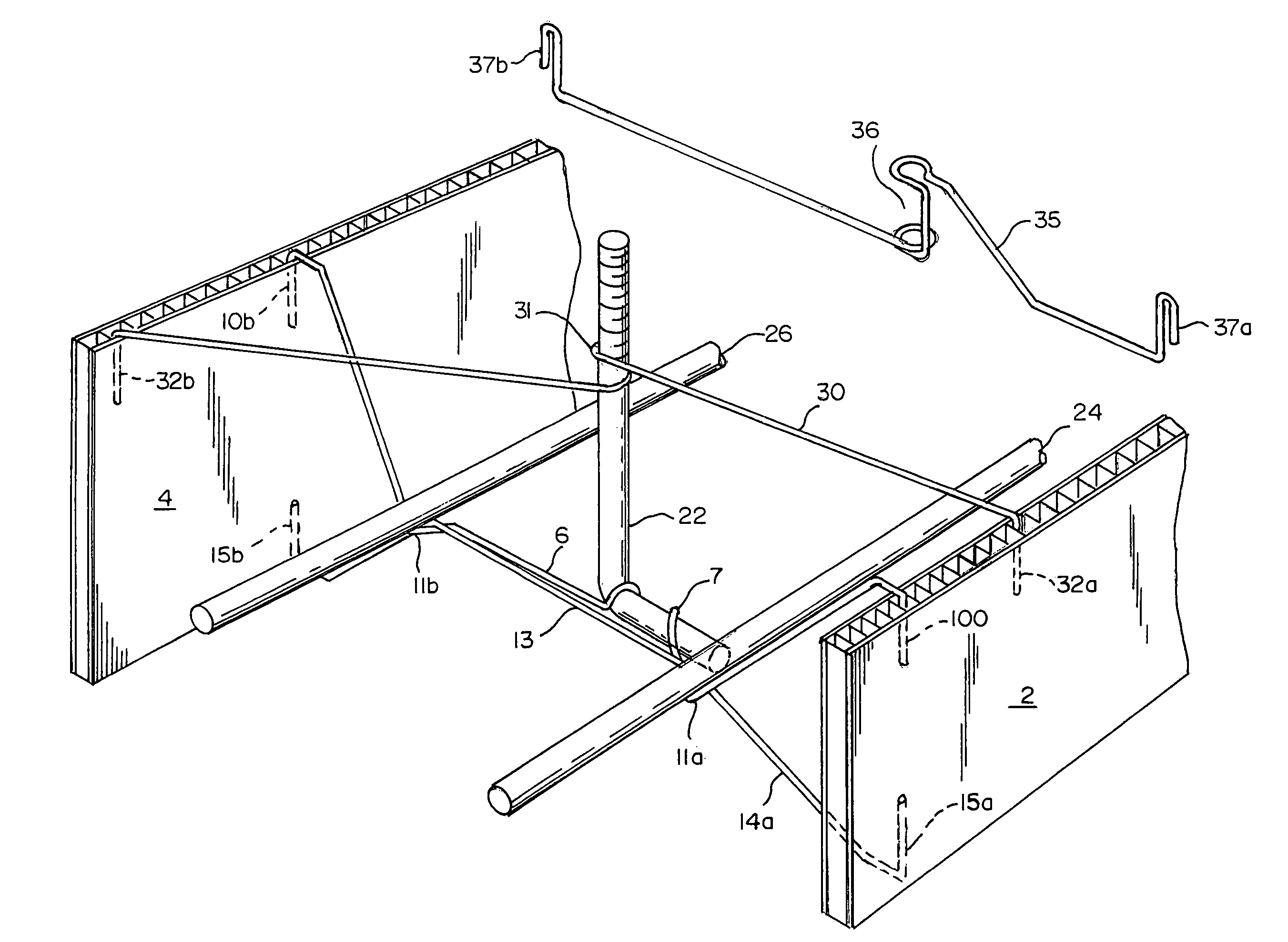
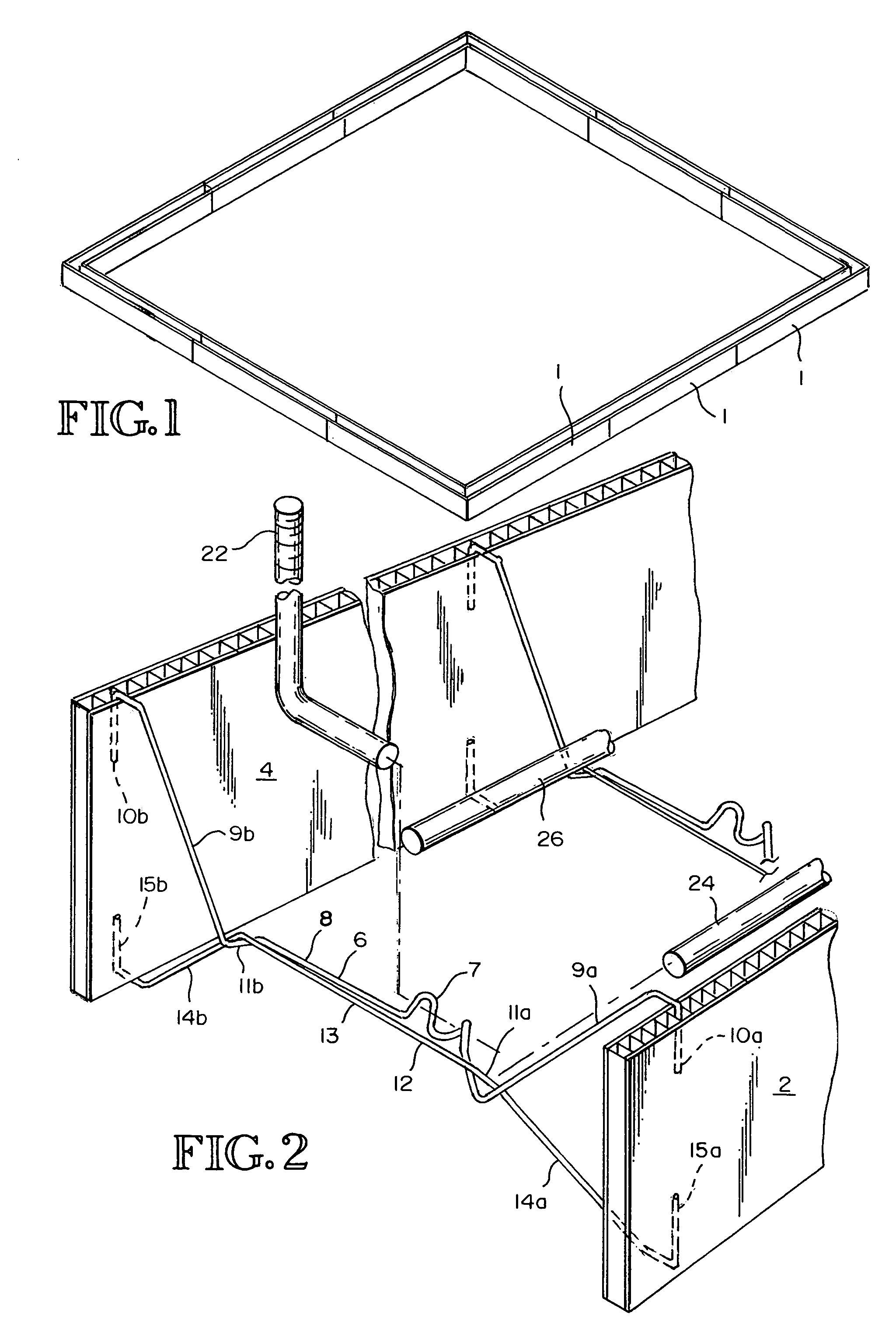
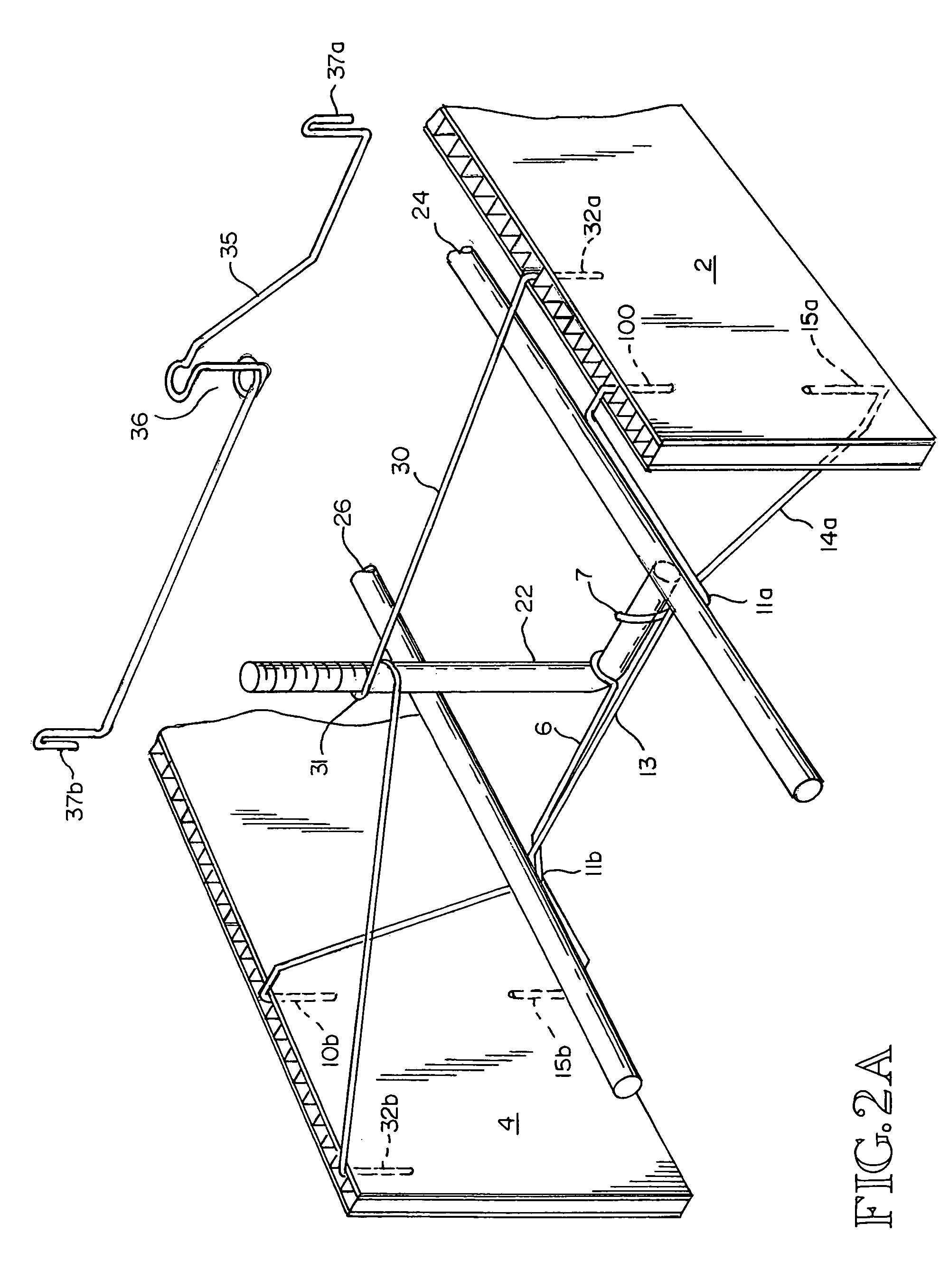
[0049]FIG. 1 shows a foundation footing form assembled from the form sections of the type that is disclosed herein. As seen in FIG. 2 the form sections of the embodiment depicted in the figure, have a pair of substantially planar side walls 2 and 4. The side walls are made from corrugated plastic having spaced, integral interconnecting ribs between two facing sheets. The channels or spaces between the interconnecting ribs are oriented at a right angle to the long axis of the form sections such that they are vertical when the form is placed on the substrate at a job site.

[0050]The side walls are connected by interconnecting top supports 6 and bottom supports 12, a plurality of which can be located along the length of the form section. In one preferred embodiment, the side walls of the form ...


PUM

PropertyMeasurementUnit
lengthaaaaaaaaaa
lengthaaaaaaaaaa
areaaaaaaaaaaa

Abstract

Moisture resistant foundation footing form sections constructed from corrugated plastic are disclosed. Supports for holding sections of reinforcing bar, and connecting the side walls of the form sections are included. Also disclosed are tabs and notches in the side walls for use with stakes to connect adjacent form sections. Form sections are disclosed for constructing a corner in a foundation footing form. Step-down forms are disclosed for constructing a foundation footing form on a construction site having surfaces of different elevations. The form sections can be secured in position with stakes, and leveling devices for leveling the form once it is secured in position are disclosed. The form sections disclosed herein can be reused, but they do not attract insects and therefore they do not have to be removed from finished foundation footings.

Description

CROSS REFERENCE TO RELATED APPLICATION[0001]This application claims the benefit of U.S. Provisional Application Ser. No. 60 / 480,896, entitled CONCRETE FORM FOR FOUNDATION FOOTING, filed Jun. 23, 2003.TECHNICAL FIELD[0002]The disclosure herein relates to an apparatus and method for forming concrete footings, for use in building construction. In particular, this document describes lightweight and collapsible forms, devices for holding re-enforcing bar in the forms, and a method for using the forms.BACKGROUND OF THE INVENTION[0003]In the art of building construction it is common practice to cast the base or foundation with concrete. A trench or excavation channel is prepared into which the forms, either made from steel or wood, are set up adjacent and connected to each other matching the dimensions of the required foundation (footing). The forms, which are steel panels or wooden boards or planks, are put into position on their edges across from each other and parallel to each other nea...

Claims


Application Information

Patent Timeline
Patent Type & Authority Patents(United States)
IPC IPC(8): E04G17/12B22D19/02E02D27/01E04B1/41E04B1/61E04B2/86E04C5/16E04G9/05E04G13/00E04G13/02E04G17/00E04G21/18
CPCE02D27/01E04B1/4157E04C5/166E04C5/167E04C5/168E04G9/05E04G13/00E04G13/02E04G17/001E04G17/12E04G21/185E04B1/6179E04B2/8635E04B2/8652E04B2001/4192E04B2001/6195E04B2002/867E04B2002/8676
Inventor HUBER, DONALD G.HARTMAN, TERRY
Owner HUBER DONALD G
Why Eureka
Try Eureka