Quick-change insert for tools, especially for thread drills

a technology of inserts and tools, applied in the direction of turning apparatuses, large fixed members, maintainance and safety accessories, etc., can solve the problems of limited adaptability of thread-cutting chucks of this type to shank ends of tools having different lengths and to quick-change inserts having different lengths, so as to increase the reliability of clamping, the effort is simplified and reduced

Inactive Publication Date: 2007-07-17
OTTO BILZ WERKZEUGFAB
View PDF23 Cites 8 Cited by
  • Summary
  • Abstract
  • Description
  • Claims
  • Application Information

AI Technical Summary

Benefits of technology

[0004]The present invention is based on the task of realizing a minimum lubrication of tools, in particular thread drills, that are held in thread-cutting chucks using quick-change inserts, with quick-change inserts having any length and to hereby increase the reliability of clamping in the region of the quick-change inserts.
[0006]Due to the fact that the quick-change insert is provided with a sealing body containing a central passage in a rear receptacle of its insert body, the sealing body producing the connection between the chuck-side lubricant channel and the lubricant bore of the particular tool that is retained in the quick-change insert, a central, closed and leakproof guidance of lubricant in the form of aerosol from the chuck to the tool is created in a simple manner, whereby rear ends of tools having different lengths are already accommodated in the quick-change insert by the automatic adjustment of the sealing body. If necessary, quick-change inserts having different sizes can be kept on hand, the quick-change inserts fitting in the same chuck but enabling an inner adaptation to different-length rear ends of receiving tools. Effort has been simplified and reduced due to the present invention. As a result of the resilient pressing of the sealing body to the shank end of the tool, the sealing body results in simultaneous clamping of the tool in the quick-change insert, thereby increasing the reliability of the clamping.

Problems solved by technology

The ability of thread-cutting chucks of this type to adapt to shank ends of tools having different lengths and to quick-change inserts having different lengths is limited, however.

Method used


Image

  • Quick-change insert for tools, especially for thread drills
  • Quick-change insert for tools, especially for thread drills

Examples


Embodiment Construction

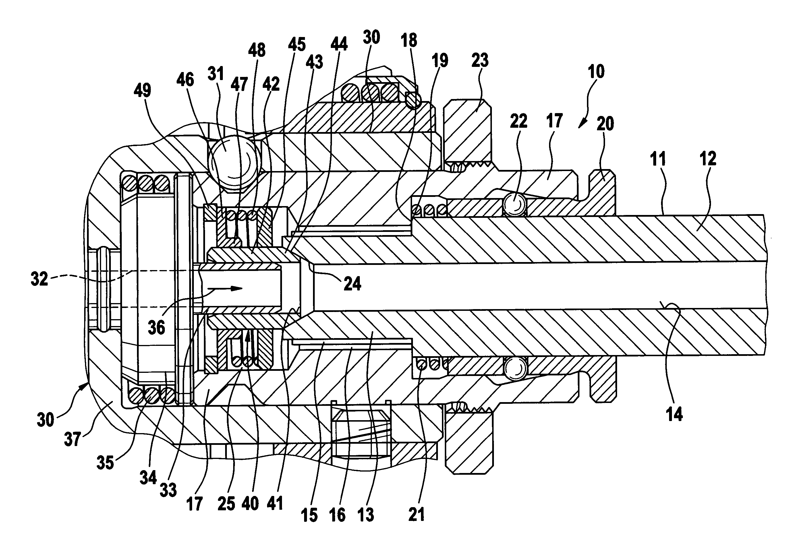
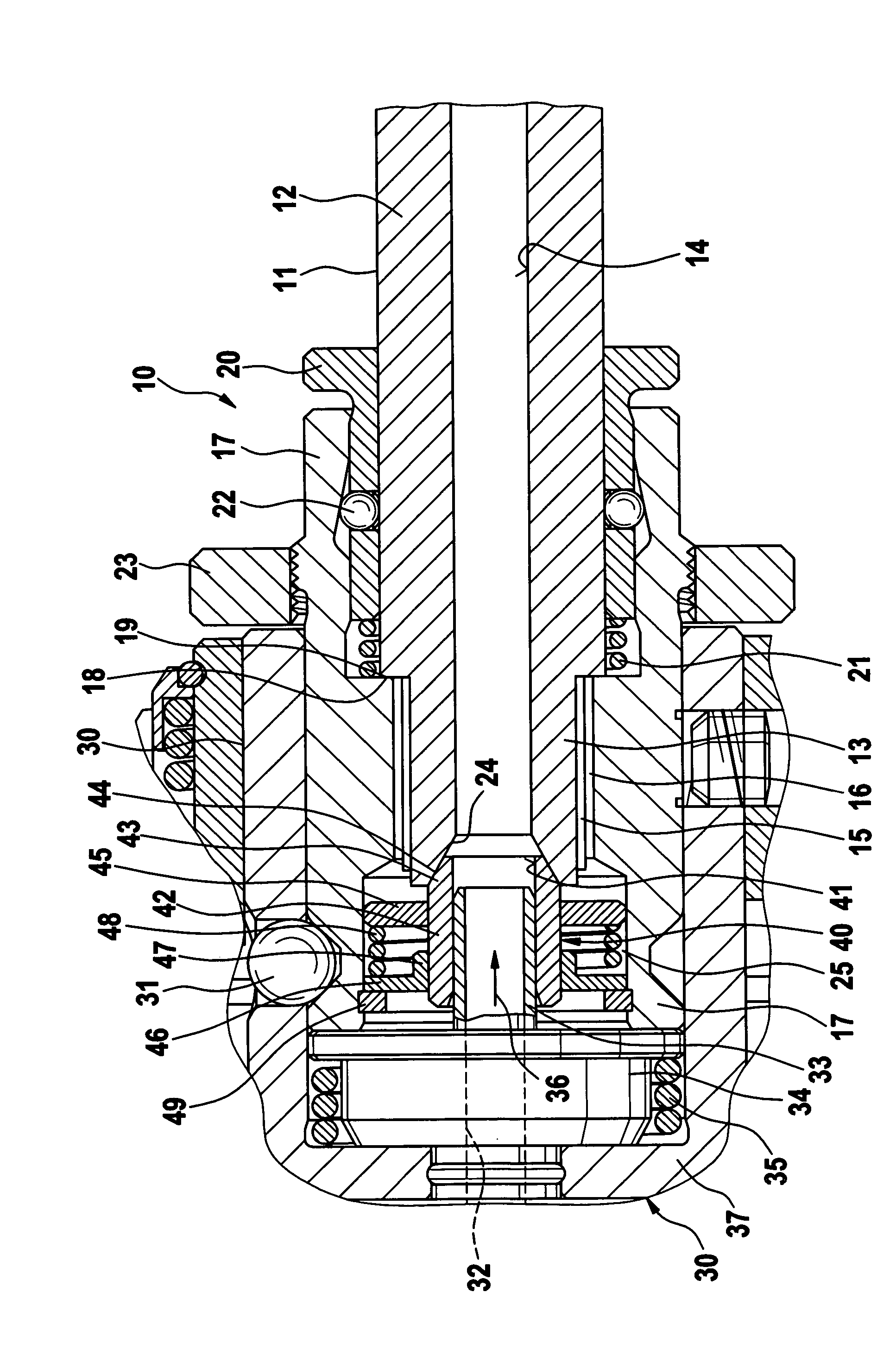
[0008]Quick-change insert 10 shown contains a tool 11, in particular a thread drill 12, which is inserted axially in quick-change insert 10 with its rear end 13 first and contains a longitudinal bore 14 for passage of a lubricant, in the form of an aerosol in particular. Tool 11 is squared 15 on the end and is accommodated via this squared configuration in a corresponding square-shaped receptacle 16 of an insert body 17 of quick-change insert 10 in a torque-transferring manner. Via an annular shoulder 18, tool 11 bears axially against a corresponding surface 19 of insert body 17. A ball bush 20 accommodated on the right (as shown in the drawing) end of insert body 17 is pressed toward the right (as shown in the drawing) by a spring 21 such that balls 22 contained in ball bush 20 are pressed radially inwardly by conical surfaces 23 that taper toward the right (as shown in the drawing) and are pressed onto the outer circumferential surface of tool 11, by way of which the tool is held ...


PUM

PropertyMeasurementUnit
diameteraaaaaaaaaa
pressureaaaaaaaaaa
lengthsaaaaaaaaaa

Abstract

The present invention relates to a quick-change insert (10) for tools (11), in particular thread drills (12), for minimal lubrication, that is designed for detachable installation in a chuck (30) provided with a central lubricant channel (32) and for introducing the lubricant as an aerosol from the lubricant channel (32) into the rear end of a longitudinal bore (14) of an inserted tool (11). A sealing body (40) provided with a central passage (41) is located in a rear receptacle (25) of the insert body (17) such that, when the tool (11) is inserted and installed in the chuck (30), it connects the lubricant channel (32) and the longitudinal bore (14) of the tool (11) with each other in an at least substantially leakproof manner.

Description

CROSS-REFERENCE[0001]The invention described and claimed hereinbelow is also described in German Patent Application DE 10 2004 021 082.9, filed Apr. 29, 2004. This German Patent Application, whose subject matter is incorporated here by reference, provides the basis for a claim of priority of invention under 35 U.S.C. 119(a)-(d).BACKGROUND OF THE INVENTION[0002]The present invention relates to a quick-change insert for tools, in particular for thread drills.[0003]A quick-change insert of this type is known (EP 0 956 919 B1) that is capable of being installed in a thread-cutting chuck for minimal lubrication and, in fact, in an insertion bush of this chuck. The thread-cutting chuck is designed for minimal lubrication and, to this end, is equipped with an axially central lubricant passage for connecting the insertion bush with a machine-side minimal lubrication source, from which the lubricant is guided as an aerosol to the longitudinal bore of the tool. In its opening region into the ...

Claims


Application Information

Patent Timeline
Patent Type & Authority Patents(United States)
IPC IPC(8): B23Q11/10B23B31/00B23Q1/00
CPCB23B31/005B23B2250/12Y10T408/455Y10T408/45Y10T279/17111Y10T408/95Y10T408/44
Inventor VOSS, MICHAELBABEL, GERHARD
Owner OTTO BILZ WERKZEUGFAB
Why Eureka
Try Eureka