Digital phase-locked loop device for synchronizing signal and method for generating stable synchronous signal

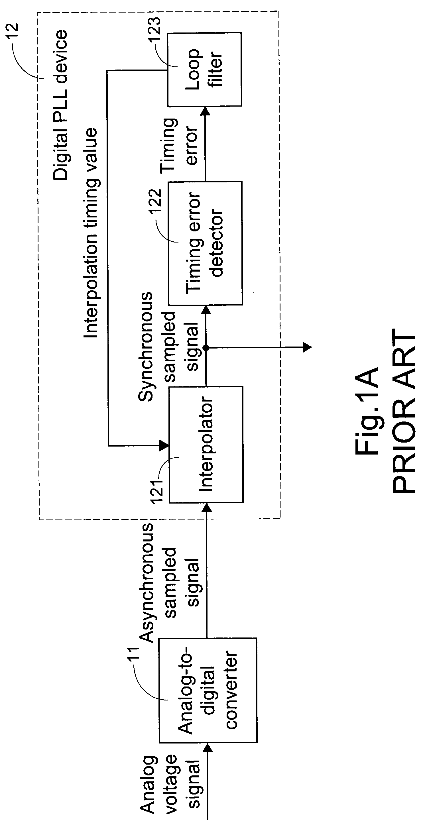
a phase-locked loop and synchronizing signal technology, applied in the direction of digital transmission, pulse automatic control, transmission, etc., can solve the problems of affecting the data pick-up performance of the data pick-up device, affecting the normal condition of the all-digital pll b>12/b>, and extremely unstable timing of the asynchronous sampled signal generated from the analog-to-digital converter b>11/b>, etc., to achieve the effect o

Inactive Publication Date: 2007-07-17
TIAN HLDG
View PDF1 Cites 10 Cited by
  • Summary
  • Abstract
  • Description
  • Claims
  • Application Information

AI Technical Summary

Benefits of technology

[0005]An object of the present invention is to provide a digital phase-locked loop (PLL) device and a signal generation method for use in a data pick-up device with the digital phase-locked loop (PLL) device, which involve in reduced converging time after the unexpected factors causing the noise are removed.

Problems solved by technology

When the analog voltage signal from the pick-up head involves therein significant noise resulting from unexpected factors such as scratch on the disk face, the timing of the asynchronous sampled signal generated from the analog-to-digital converter 11 is extremely unstable.
Therefore, it will take a long time for the all-digital PLL 12 to recover the normal condition after the unexpected factors are removed.
Thus, the data pick-up performance of the data pick-up device is adversely affected.

Method used


Image

  • Digital phase-locked loop device for synchronizing signal and method for generating stable synchronous signal
  • Digital phase-locked loop device for synchronizing signal and method for generating stable synchronous signal
  • Digital phase-locked loop device for synchronizing signal and method for generating stable synchronous signal

Examples


Embodiment Construction

[0026]The present invention will now be described more specifically with reference to the following embodiments. It is to be noted that the following descriptions of preferred embodiments of this invention are presented herein for purpose of illustration and description only; it is not intended to be exhaustive or to be limited to the precise form disclosed.

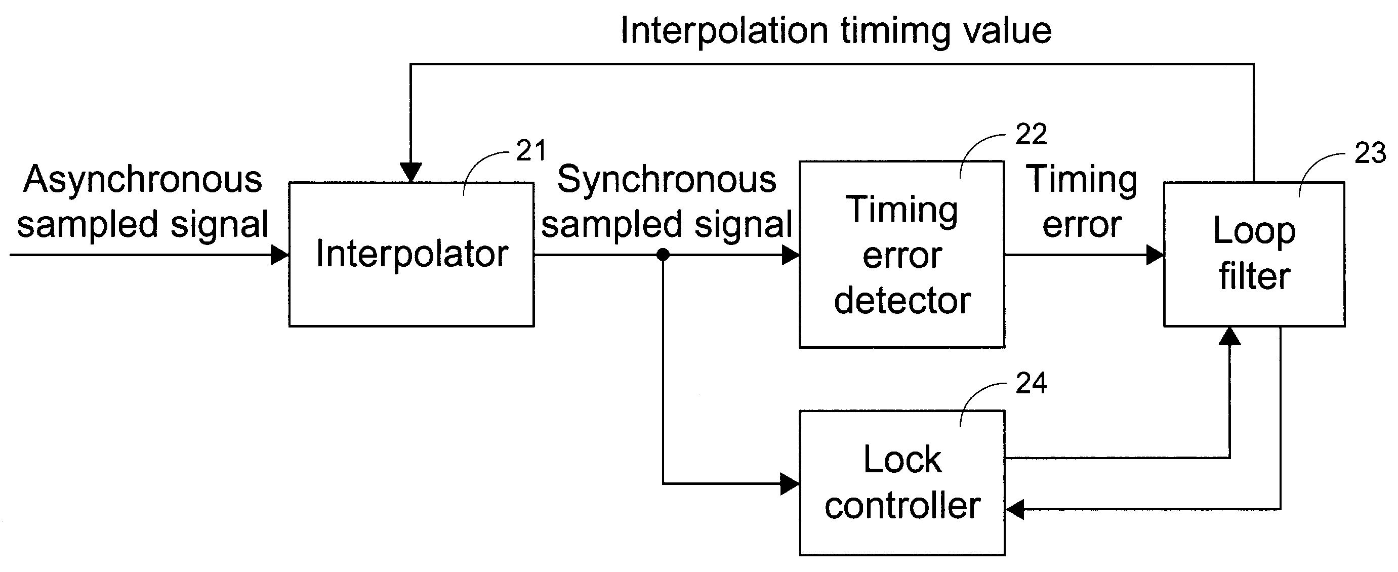
[0027]FIG. 2 schematically illustrates a preferred embodiment of an all-digital phase-locked loop (PLL) device for use in an optical-disk pick-up device according to the present invention. The all-digital PLL device includes an interpolator 21, a timing error detector 22, a loop filter 23 and a lock controller 24. The interpolator 21 receives and processes an asynchronous sampled signal in response to an interpolation timing value to output a synchronous sampled signal. The timing error detector 22 electrically connected the interpolator 21 detects a timing error value between the synchronous sampled signal and an expected synchr...


PUM


Abstract

A phase-locked loop (PLL) device is disclosed. The PLL device includes an interpolator receiving and processing an input signal by an interpolation operation in response to an interpolation timing value to obtain an output signal, a timing error detector in communication with the interpolator for detecting a timing error value of the output signal, a loop filter in communication with the timing error detector for outputting the interpolation timing value to the interpolator in response to the timing error value, and a lock controller in communication with the loop filter for adjusting the interpolation timing value according to a timing quality of the output signal, and providing the adjusted interpolation timing value for the interpolator. A signal generation method for use in the data pick-up device with the aid of the digital phase-locked loop (PLL) device is also disclosed.

Description

FIELD OF THE INVENTION[0001]The present invention relates to a digital phase-locked loop (PLL) device, and more particularly to a digital phase-locked loop (PLL) device for use in a data pick-up device. The present invention also relates to a method for generating a signal for use in the data pick-up device with the aid of the digital phase-locked loop (PLL) device.BACKGROUND OF THE INVENTION[0002]Please refer to FIG. 1A which is a partial functional block diagram illustrating a conventional data pick-up device, e.g. an optical-disk pick-up device. An analog voltage signal from a pick-up head (PUH) is converted into an asynchronous sampled signal by an analog-to-digital converter (ADC) 11. Subsequently, the asynchronous sampled signal is adjusted by an all-digital phase-locked loop (PLL) device 12 to output a synchronous sampled signal. The all-digital PLL device 12 includes an interpolator 121, a timing error detector 122 and a loop filter 123. The interpolator 121 receives and pro...

Claims


Application Information

Patent Timeline
Patent Type & Authority Patents(United States)
IPC IPC(8): H03D3/24H03L7/091H03L7/093H03L7/095
CPCH03L7/091H03L7/093H03L7/095H03L2207/50
Inventor CHANG, CHRIS
Owner TIAN HLDG
Why Eureka
Try Eureka