Photonic channelized RF receiver employing dense wavelength division multiplexing

a wavelength division multiplexing and receiver technology, applied in the field of photonic channelized receivers, can solve the problems of not providing a near real-time wideband spectral monitoring ability, preventing the ability to detect burst signals, and rf spectrum analyzers, etc., to achieve high reliability and sensitivity, and reliably detect short-duration burst signals

Active Publication Date: 2007-07-17
HARRIS CORP
View PDF10 Cites 51 Cited by
  • Summary
  • Abstract
  • Description
  • Claims
  • Application Information

AI Technical Summary

Benefits of technology

[0010]Another object of the present invention is to provide the capability to reliably detect short-duration burst signals over a frequency band of interest.
[0011]Yet a further object of the present invention is to employ a channelized receiver design having high reliability and sensitivity and being capable of processing a large number of channels.
[0017]In accordance with another embodiment, the laser sources of the photonic channelized are modulated by the RF signal prior to being combined into a common beam. This approach eliminates the need for an electro-optical phase modulator between the optical combiner and the etalon but requires separate modulation of each of the optical signals.

Problems solved by technology

The principle shortcoming of RF spectrum analyzers is that they do not provide a near real time wideband spectral monitoring ability.
This approach precludes the ability to detect burst signals that exist for times shorter than the period of time required to sweep the band.
However, they are complex, have limited reliability and sensitivity, and are impractical if a large number of channels is required.
However, electro-optical devices suffer from the inability to be implemented entirely in standard, commercial off-the-shelf (COTS) optical fiber components.

Method used


Image

  • Photonic channelized RF receiver employing dense wavelength division multiplexing
  • Photonic channelized RF receiver employing dense wavelength division multiplexing
  • Photonic channelized RF receiver employing dense wavelength division multiplexing

Examples


Embodiment Construction

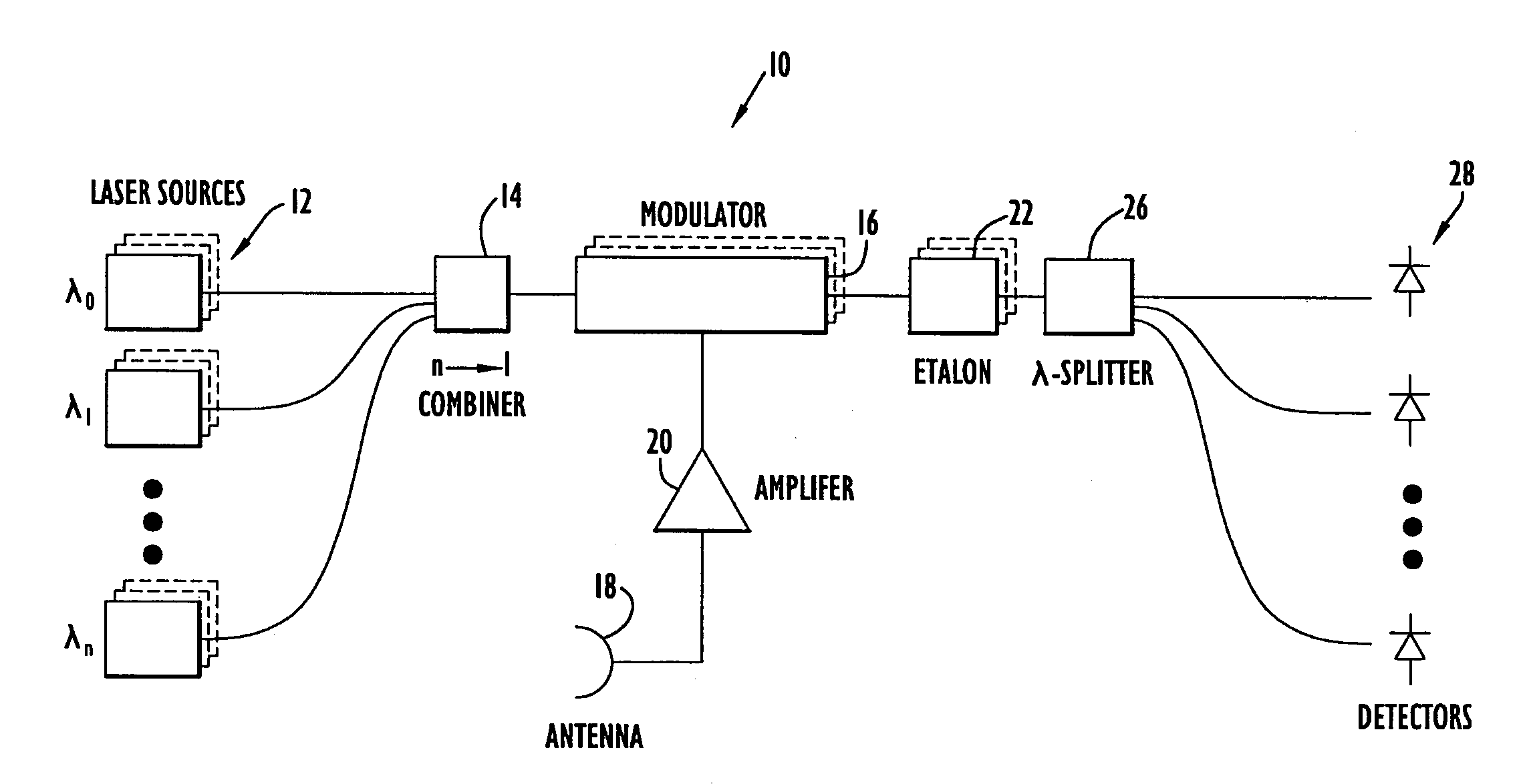
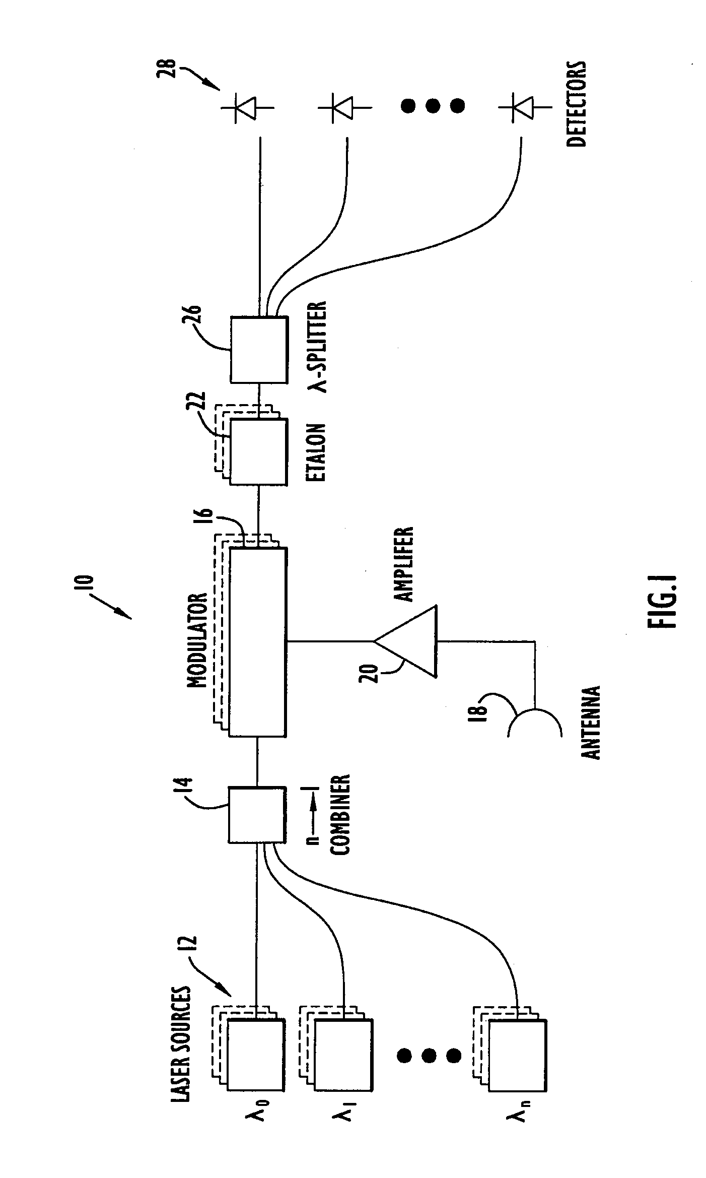
[0022]A photonic channelized receiver 10 useful for RF spectrum analysis is illustrated in FIG. 1. Receiver 10 includes a set of laser sources 12 that supply a respective set of optical signals whose wavelengths are separated by substantially equal spacings. Specifically, a first laser source generates an optical signal at a particular wavelength λ0. The second laser source generates an optical signal at a longer wavelength λ1. Since these optical signals are used to define receiver frequency channels, their separation can be described in terms of frequency. For example, the optical signal at λ0 can be separated from the optical signal at λ1 by a nominal frequency of 99.5 GHz. An optical signal generated by a next laser source at a next longer wavelength λ2 is separated from the optical signal at λ1 by another 99.5 GHz, and each successive optical signal generated up to wavelength λn is separated from optical signals at adjacent wavelengths by 99.5 GHz. In this manner, a set of equa...


PUM


Abstract

A photonic channelized receiver includes: an optical source, an optical combiner, an electro-optical modulator, an etalon, a wavelength splitter, and a set of detectors. The optical source produces a set of optical signals at spaced wavelengths, and the optical combiner combines the optical signals into a common beam. The electro-optical modulator modulates the common beam with an RF signal to produce sidebands offset from frequencies of the optical signals by the RF signal frequency. The etalon has a periodic transfer function that filters the modulated common beam such that the signals in the filtered, modulated common beam function as receiver channels corresponding to respective RF frequencies. The wavelength splitter separates the common beam into channel output signals whose intensities are a function of the frequency of the RF signal. The detectors measure the intensities of the channel output signals to determine the frequency of the RF signal.

Description

CROSS REFERENCE TO RELATED APPLICATION[0001]This application claims priority from U.S. Provisional Patent Application Ser. No. 60 / 426,403, entitled “Dense Wavelength Division Multiplexing Based Photonic RF Spectrum Analyzer,” filed Nov. 15, 2002. The disclosure of this provisional patent application is incorporated herein by reference in its entirety.BACKGROUND OF THE INVENTION[0002]1. Field of the Invention[0003]The present invention relates to a photonic channelized receiver that employs Dense Wavelength Division Multiplexing (DWDM) technology and, more particularly, to a photonic channelized receiver useful for RF spectrum analysis.[0004]2. Description of the Related Art[0005]Electronic spectrum analyzers and channelized receivers for microwave and RF spectrum characterization applications are similar in operation in that they separate a wideband signal into a number of narrower individual channels. The electronic spectrum analyzer operates by scanning a narrow bandpass filter ov...

Claims


Application Information

Patent Timeline
Patent Type & Authority Patents(United States)
IPC IPC(8): H04B10/00H04B10/06H04B10/08H04B17/00
CPCH04B10/2575H04B10/66H04J14/02H04J14/0298H04B2210/006
Inventor VOLKENING, FRED ALLAN
Owner HARRIS CORP
Why Eureka
Try Eureka