Methods and apparatus for operating gas turbine engines

a gas turbine engine and gas turbine technology, applied in the direction of machines/engines, vessel construction, marine propulsion, etc., can solve the problems of adversely affecting engine performance, adversely affecting engine specific fuel consumption (sfc), and substantial noise produced along the take-off path of aircraft, so as to facilitate the generation of a streamwise vortex downstream

Inactive Publication Date: 2007-07-24
GENERAL ELECTRIC CO
View PDF18 Cites 58 Cited by
  • Summary
  • Abstract
  • Description
  • Claims
  • Application Information

AI Technical Summary

Problems solved by technology

During such operations, as the high velocity flows interact with each other and with ambient air flowing past the engine, substantial noise may be produced along the take-off path of the aircraft.
Although the tabs, mixing lobes, and chevrons facilitate suppressing noise during high power engine operating conditions, because the tabs, mixing lobes, and chevrons are mechanical devices which remain positioned in the flow path during all flight conditions, such devices may adversely impact engine performance during non-take-off operating conditions.
Specifically, during cruise conditions, the tabs, the mixing lobes, and / or the chevrons may adversely impact specific fuel consumption (SFC) of the engine.

Method used


Image

  • Methods and apparatus for operating gas turbine engines
  • Methods and apparatus for operating gas turbine engines
  • Methods and apparatus for operating gas turbine engines

Examples


Embodiment Construction

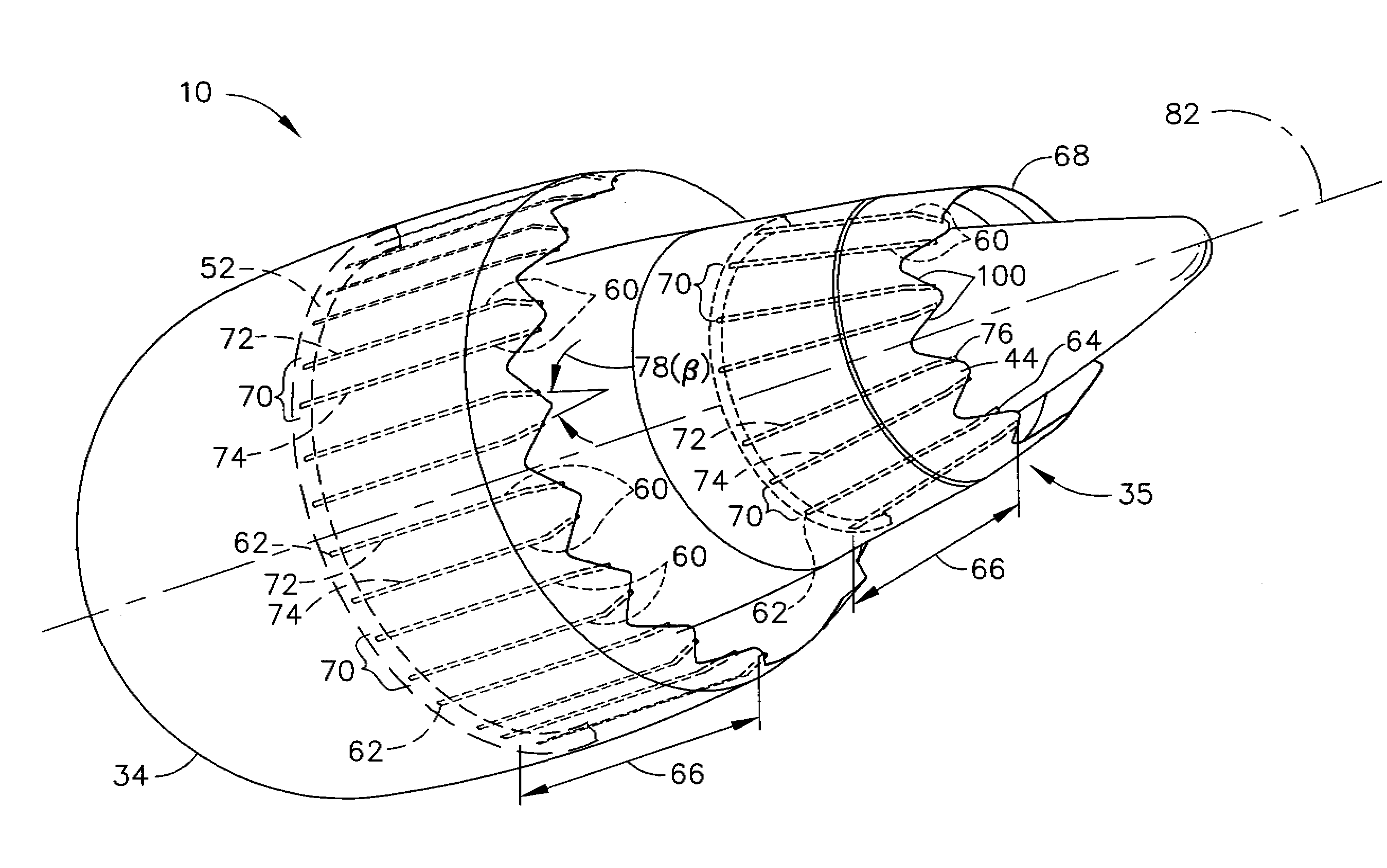
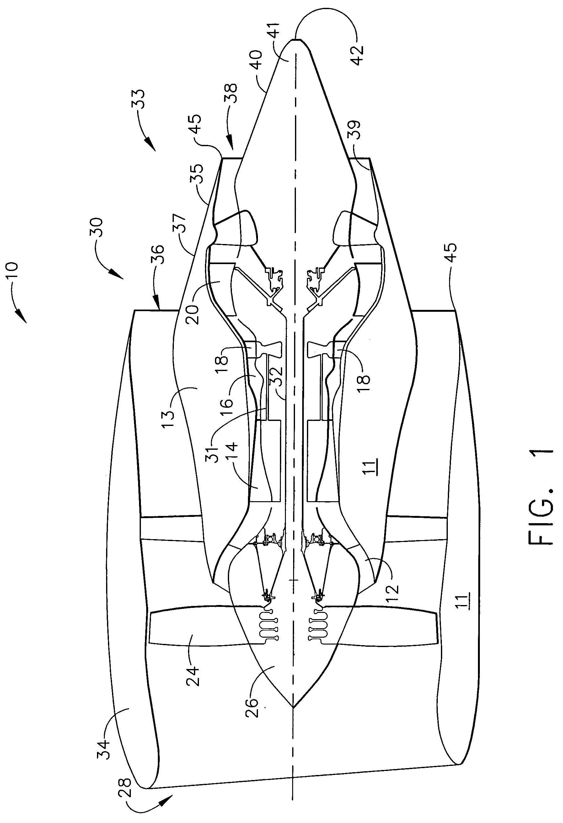
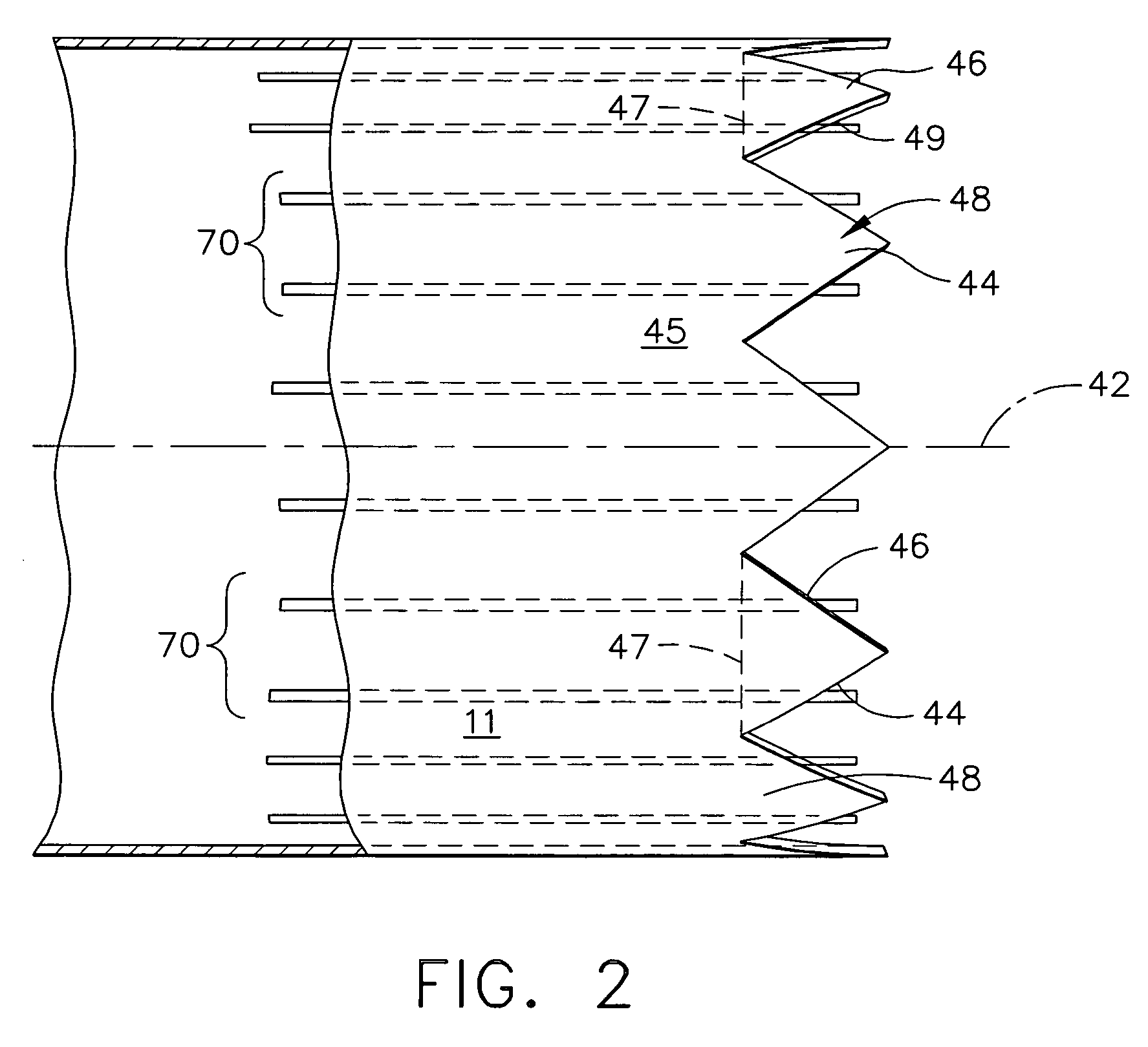
[0014]FIG. 1 is a schematic illustration of a gas turbine engine 10 including a fan assembly 12 and a core engine 13 including a high pressure compressor 14, and a combustor 16. FIG. 2 is a side view of an exemplary nozzle design 11 that may be used with gas turbine engine 10. Engine 10 also includes a high pressure turbine 18, and a low pressure turbine 20. Fan assembly 12 includes an array, of fan blades 24 extending radially outward from a rotor disc 26. Engine 10 has an intake side 28 and an exhaust side 30. In one embodiment, the gas turbine engine is a GE90 available from General Electric Company, Cincinnati, Ohio. Fan assembly 12 and turbine 20 are coupled by a first rotor shaft 31, and compressor 14 and turbine 18 are coupled by a second rotor shaft 32.

[0015]An exhaust assembly 33 extends downstream from core engine 13 and includes an annular fan exhaust nozzle 34 that extends around, and is spaced radially outwardly from, a core engine exhaust nozzle 35. More specifically, ...


PUM


Abstract

A method for operating a gas turbine engine includes channeling compressed air from the gas turbine engine to a noise suppression system, and selectively operating the noise suppression system such that air discharged from the noise suppression system generates a streamwise vortex downstream from each respective chevron.

Description

BACKGROUND OF THE INVENTION[0001]This invention relates generally to gas turbine engines, and more particularly to methods and apparatus for operating gas turbine engines.[0002]At least some known gas turbine engines include a core engine having, in serial flow arrangement, a fan assembly and a high pressure compressor which compress airflow entering the engine, a combustor which bums a mixture of fuel and air, and low and high pressure rotary assemblies which each include a plurality of rotor blades that extract rotational energy from airflow exiting the combustor.[0003]Combustion gases are discharged from the core engine through an exhaust assembly. More specifically, within at least some known turbofan engines, a core exhaust nozzle discharges core exhaust gases radially inwardly from a concentric fan exhaust nozzle which exhausts fan discharge air therefrom for producing thrust. Generally during engine operation, both exhaust flows approach their maximum velocity during high pow...

Claims


Application Information

Patent Timeline
Patent Type & Authority Patents(United States)
IPC IPC(8): F02K1/34F02K1/40F01D1/00F02K1/38F02K1/48
CPCF02K1/386F02K1/48B64D2033/024
Inventor GUTMARK, EPHRAIM JEFFMARTENS, STEVEN
Owner GENERAL ELECTRIC CO
Why Eureka
Try Eureka