Progressive solar based power generating system

a solar energy and power generation system technology, applied in the field of apparatus, can solve the problems of affecting the continuous energy conversion of solar energy to electricity, affecting the efficiency of the system, and affecting the efficiency of the system, and achieve the effect of environmental protection and cost-effectiveness

Active Publication Date: 2007-07-24
HENDRIX JOHN PERRY +2
View PDF4 Cites 15 Cited by
  • Summary
  • Abstract
  • Description
  • Claims
  • Application Information

AI Technical Summary

Benefits of technology

[0015]It is a further object of the present invention to provide a progressive solar based power generating system that is continuous, cost effective and environmentally sound.

Problems solved by technology

The main disadvantage of these systems is that they can only function when the solar energy is available.
Clearly, the solar energy is only available when the sun is present.
Therefore, conversions from solar energy to electricity by these systems are often impeded when solar radiation is not available, or insufficient, thus, inconsistent.
While these systems in the art may be suitable for the particular purpose to which they address, they are not suitable for continuous energy conversion.
Another problem with these systems in the art is that they are not capable of converting solar energy to both steam-to-rotary energy and hydroelectric energy.

Method used


Image

  • Progressive solar based power generating system
  • Progressive solar based power generating system
  • Progressive solar based power generating system

Examples


Embodiment Construction

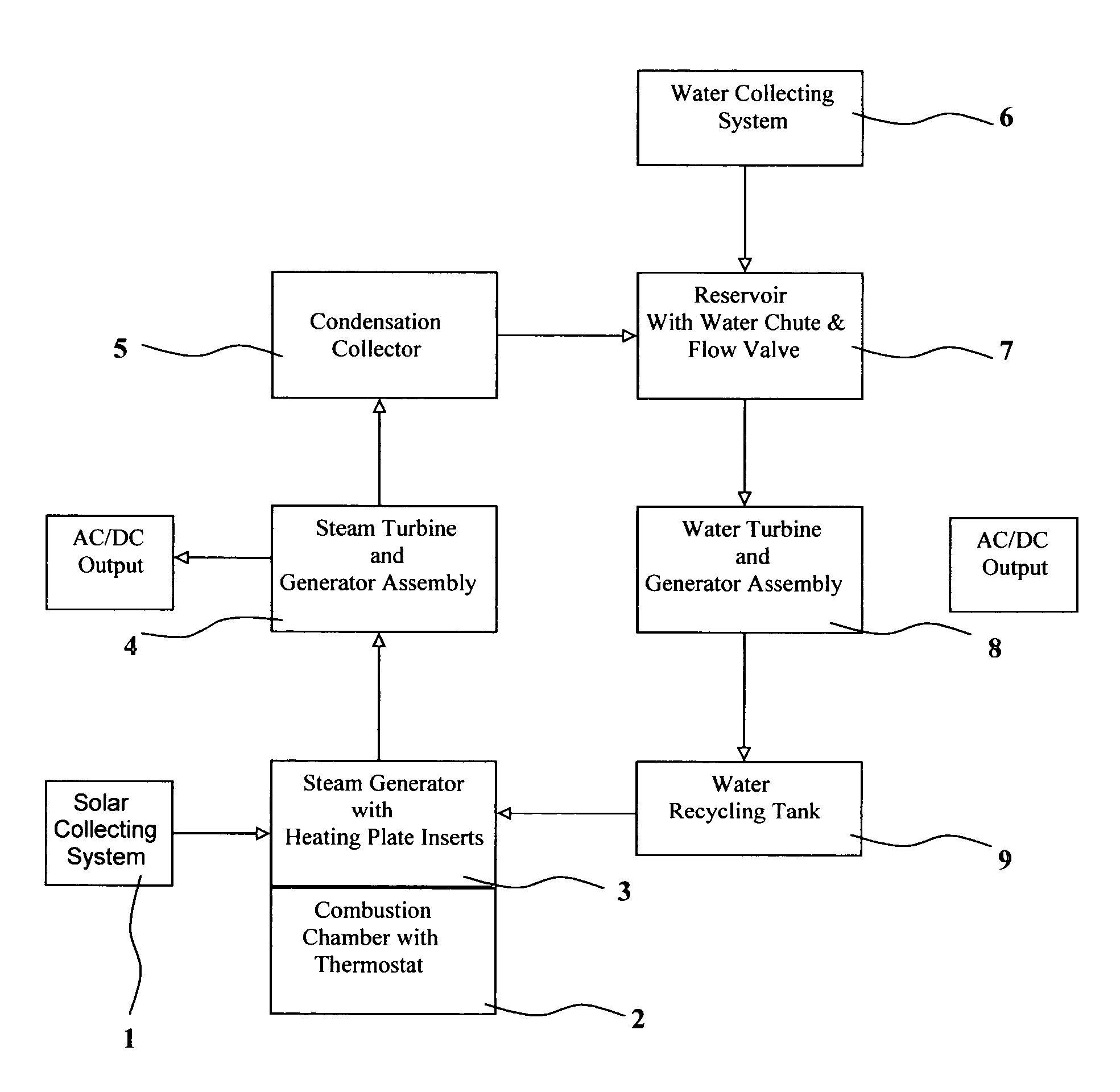
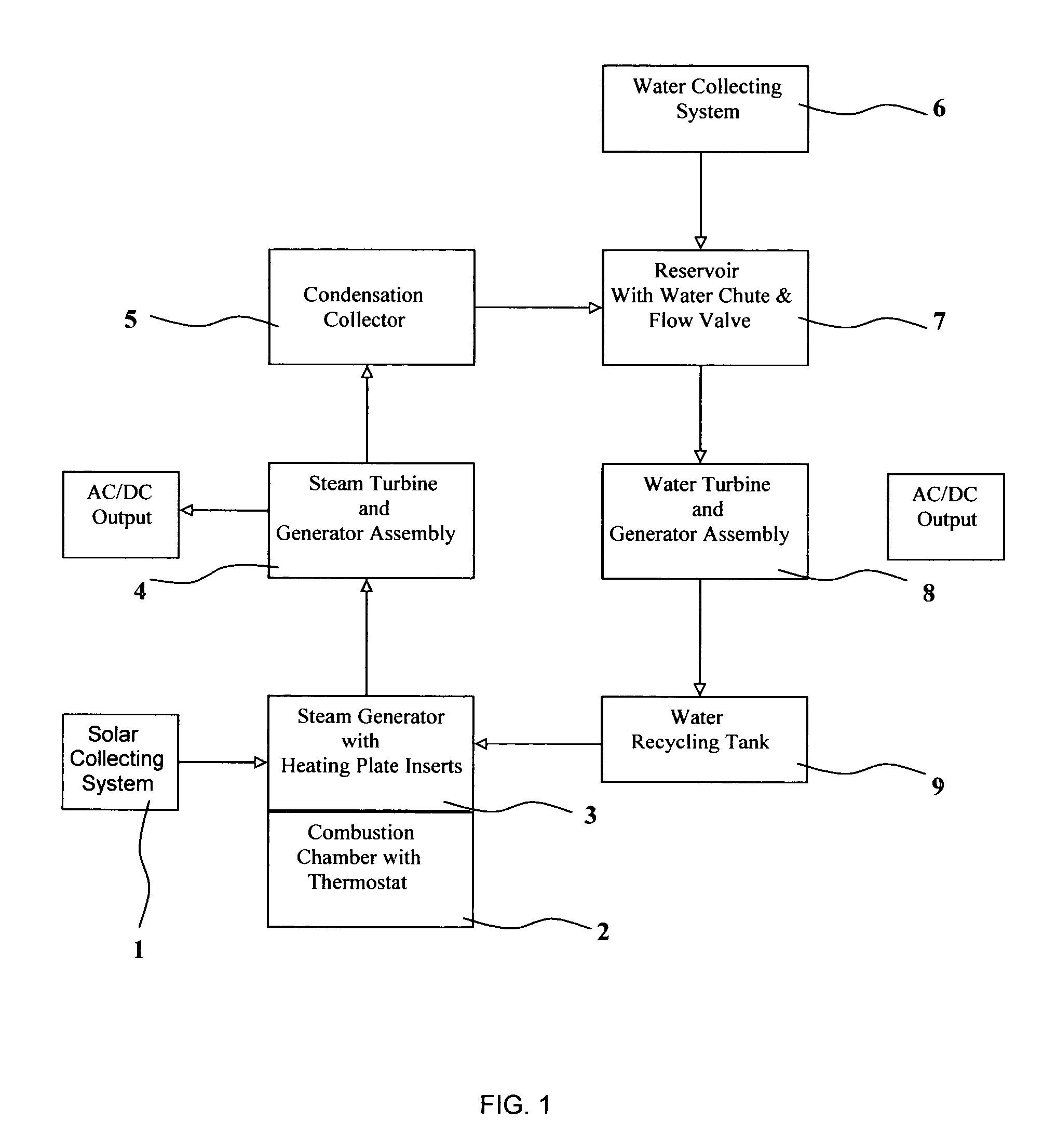
[0024]Turning now descriptively to drawings, in which similar reference characters denoted similar elements throughout the several views to designate the same components. FIG. 1 is a preferred embodiment of the apparatus of the current invention, which comprises a solar collector 1, for concentrating solar energy to steam generator 3 to produce superheated steam, a combustion chamber 2 for reinforcing the steam production when solar energy is insufficient, a steam turbine and generator assembly 4 for converting steam to electrical energy in a known manner, a condensation collector 5 for collecting leftover steam after steam-to-electrical energy conversion, a water collecting system 6 for collecting and filtering rain or water, condensed steam and water are both stored in a reservoir 7 and released to a water turbine and generator assembly 8 thereby converting water into hydroelectric energy in a known manner. The remaining water after the hydroelectric energy conversion is collected...


PUM


Abstract

An apparatus for converting solar energy to electrical energy and continue to generate electricity even when the solar radiation is not available by directing solar radiation to heating plates, which were mostly immersed in a steam generator to induce water temperature, and process water into steam which interacts with steam turbine and generator assembly to produce electricity. The remnant of the steam after steam to electricity conversion is captured by an elevated condensation collector, which is tilted with the lower side attached to a reservoir, the condensed steam descends into the reservoir, which is also elevated and attached by a water collecting system that collects rain and water from other sources. Water from the reservoir is released from the water chute at the base of the reservoir to the original elevation where it powers a water turbine and power, after electrical energy is extracted by generator assembly, the remaining water is recycled back into the steam generator for continuous solar energy conversion. A combustion chamber attached beneath the steam generator can be initiated using biomass or natural gas to ensure superheated steam production in the event that the solar radiation is unavailable or insufficient.

Description

[0001]This application claims the priority of Provisional Patent Application No. 60 / 455,775, filed on Mar. 19, 2003, of which following is a specification:BACKGROUND OF THE INVENTION[0002]1. Field of the Invention[0003]The present invention relates to an apparatus for continuous conversion of solar energy into electrical power, more specifically, to an apparatus which can direct solar radiation to a steam conversion device, to convert water into superheated steam, which is used to generate steam to rotary energy, thereby producing electrical energy, subsequently, remaining steam is captured by a condensation-collector and water collecting system, then directed to generate hydroelectric energy, and ultimately, is recycled back to the steam conversion device. A combustion chamber beneath the steam generator serves as a supplemental heating source and can be initiated when solar radiation is unavailable or insufficient to ensure the water-to-steam conversion. The process of concentrati...

Claims


Application Information

Patent Timeline
Patent Type & Authority Patents(United States)
IPC IPC(8): B60K16/00F03G6/06F24S20/20F24S23/30
CPCF03G6/065F24J2/07F24J2/08F05B2220/702Y02E10/41Y02E10/46F24S20/20F24S23/30Y02E10/40
Inventor HENDRIX, JOHN PERRYHENDRIX, MEI YUNHENDRIX, JOSHUA FONG
Owner HENDRIX JOHN PERRY
Why Eureka
Try Eureka