Washdown conveyor corner section with removable wear strips

a conveyor and corner section technology, applied in the direction of conveyor parts, transportation and packaging, rollers, etc., can solve the problems of reducing the operating time of the food processing system, requiring time-consuming disassembly, and the need for washing down of the conveyor frame section

Active Publication Date: 2007-07-24
DORNER MFG. CORP.
View PDF11 Cites 20 Cited by
  • Summary
  • Abstract
  • Description
  • Claims
  • Application Information

AI Technical Summary

Benefits of technology

[0008]The inner and outer side frames are joined to each other by a series of spaced cross supports. Preferably, each of the cross supports is welded to both the inner side frame and the outer side frame to define a corner frame. Specifically, the first end of each of the cross supports is welded to the inner surface of the inner side frame along one of the bend lines between the flat facets. The second end of each cross support is welded to the outer side frame at one of the bend lines between the outer facets. The attachment of the cross supports between the inner and outer side frames at the bend lines increases the strength of the corner frame and hides the weld line to provide a more desirable appearance for each of the side frame members.
[0010]In addition to supporting the upper run of the conveyor belt, the corner section also includes a series of support rods that extend between the inner and outer side frames to provide support for the lower run of the conveyor belt. Preferably, the first end of each support rod is removably supported by the inner side frame, while the second end of the support rod is removably supported by the outer side frame. Both ends of each support rod are received within slots formed in the respective inner and outer side frames such that the support rods can be removed and replaced without the requirement of any external tooling.

Problems solved by technology

Although prior art conveyor frame assemblies function relatively well in a sanitary environment, the wash down of the conveyor frame section typically requires the time consuming disassembly of the conveyor frame assembly prior to wash down.
The amount of time required to wash down the conveyor section disables the conveyor, thereby reducing the operating time of the food processing system.

Method used


Image

  • Washdown conveyor corner section with removable wear strips
  • Washdown conveyor corner section with removable wear strips
  • Washdown conveyor corner section with removable wear strips

Examples


Embodiment Construction

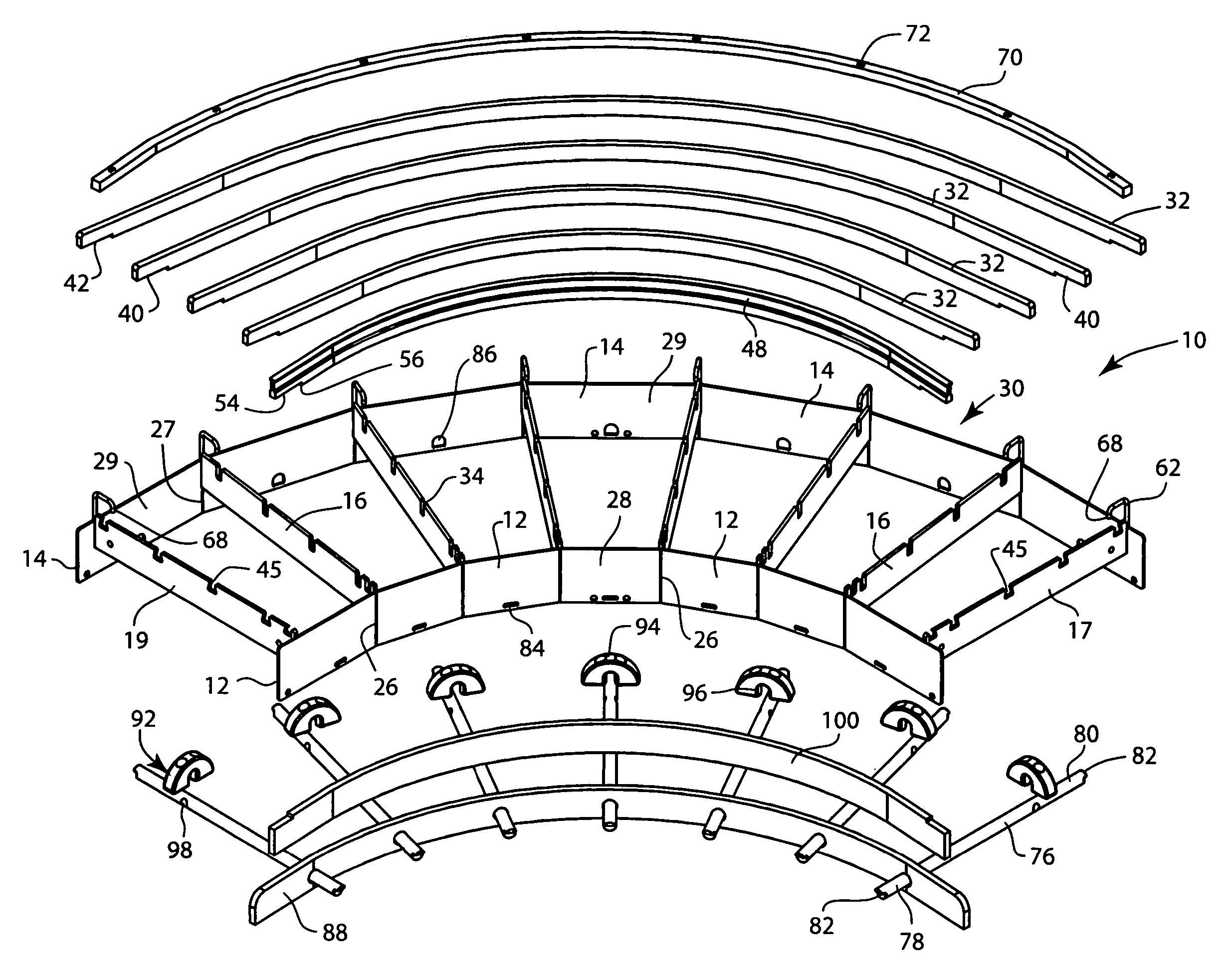
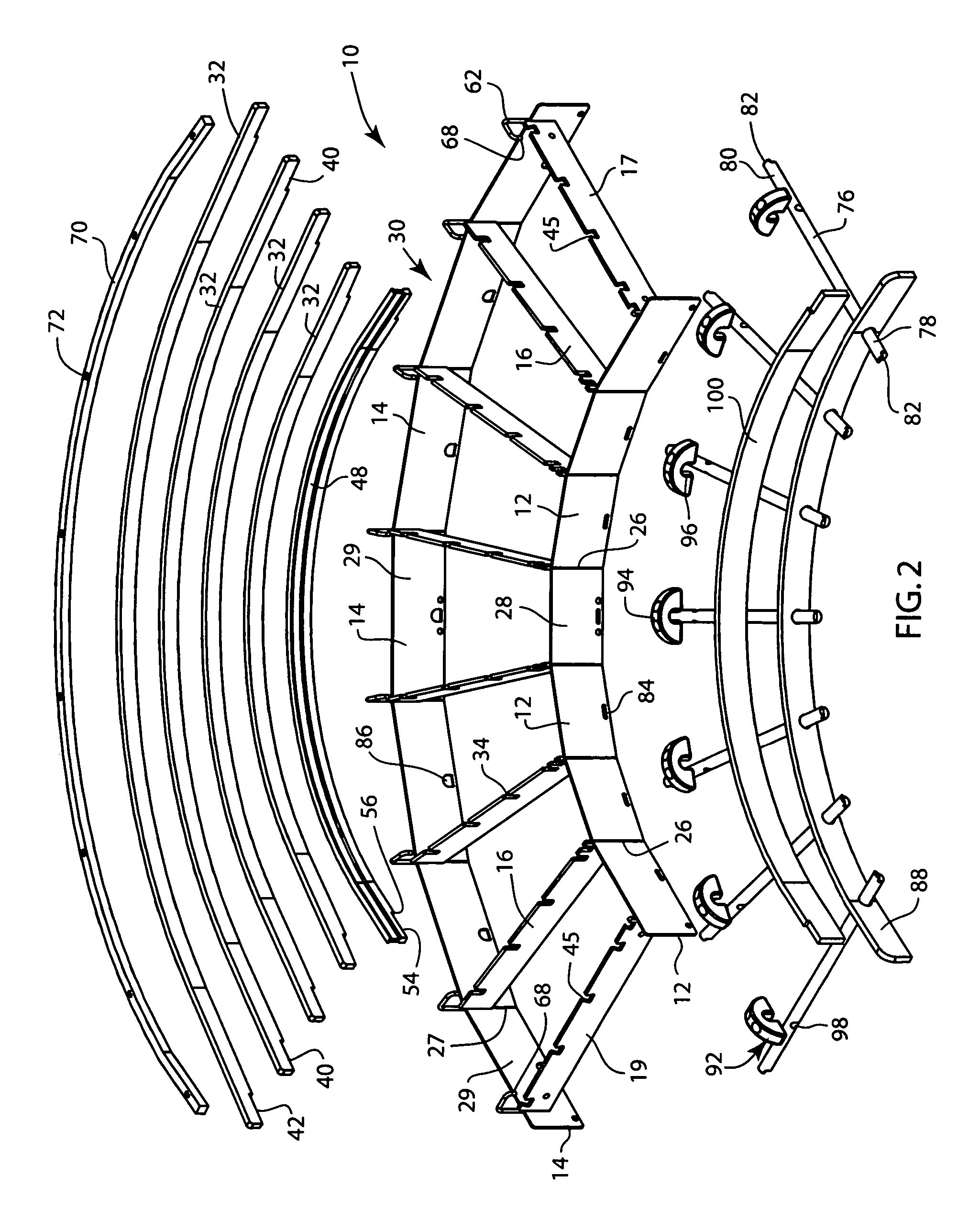
[0020]Referring first to FIG. 1, thereshown is a corner section 10 of a conveyor frame assembly constructed in accordance with the present invention. The corner section 10 is configured to receive the top and bottom runs of a continuous conveyor belt (not shown) from a straight conveyor section and provide transition for the conveyor belt into another straight conveyor section. In the embodiment of the invention illustrated in FIG. 1, the corner section 10 is a 90° corner section. However, it is contemplated that other angles for the corner section 10 are contemplated as being within the scope of the present invention.

[0021]As illustrated in FIG. 1, the corner section 10 includes an inner side frame 12 and an outer side frame 14 separated from each other by the width of the conveyor belt. As illustrated, the inner side frame 12 and the outer side frame 14 are joined to each other by a series of cross supports 16, a first end support 17 and a second end support 19. Each of the cross ...


PUM


Abstract

The present invention is a corner section of a conveyor frame assembly that includes removable slide bars and wear strips. The corner section is formed from two side frames of stainless steel joined by multiple stainless steel cross supports. Each of the cross supports is configured to receive a plurality of slide bars formed from a durable plastic material, such as UHMW. The side frames of the corner section also receive a series of support rods positioned to support the lower run of the conveyor belt. Each support rod supports a continuous, lower wear strip and a support puck. The entire corner section can be disassembled and reassembled without the requirement of any external tooling.

Description

CROSS REFERENCE TO RELATED APPLICATIONS[0001]This application is based on and claims priority from U.S. Provisional Patent Application Ser. No. 60 / 625,821 filed on Nov. 8, 2004.BACKGROUND OF THE INVENTION[0002]The present invention relates to a conveyor assembly for use in a sanitary application. More specifically, the present invention relates to a corner section for a sanitary conveyor assembly in which the corner section includes stainless steel side frame members and conveyor belt support slide bars and wear strips for supporting both the upper and lower runs of the conveyor belt that can be removed without the use of tools.[0003]Presently, conveyors used in the food processing industry must meet strict standards regarding the construction of the conveyor to avoid areas on the conveyor in which water or food product can collect. In most applications, the conveyor frame assembly is formed from a stainless steel material such that the frame assembly can be easily washed and saniti...

Claims


Application Information

Patent Timeline
Patent Type & Authority Patents(United States)
IPC IPC(8): B65G15/02B65G15/60
CPCB65G21/06B65G21/16B65G2201/0202
Inventor HOSCH, MICHAEL A.HALL, SCOTT M.ERTEL, DANIEL E.
Owner DORNER MFG. CORP.
Why Eureka
Try Eureka