
Data display device

a technology of data display and display device, which is applied in the direction of instrumentation, lighting and heating apparatus, planar/plate-like light guides, etc., can solve the problems of apparent conflict between light conductivity laws and approaches, and use of luminescent light sources, so as to increase the volume of information, the effect of uniform exposur

Inactive Publication Date: 2007-07-24
ESTRAKON
View PDF50 Cites 58 Cited by
  • Summary
  • Abstract
  • Description
  • Claims
  • Application Information

AI Technical Summary

Benefits of technology

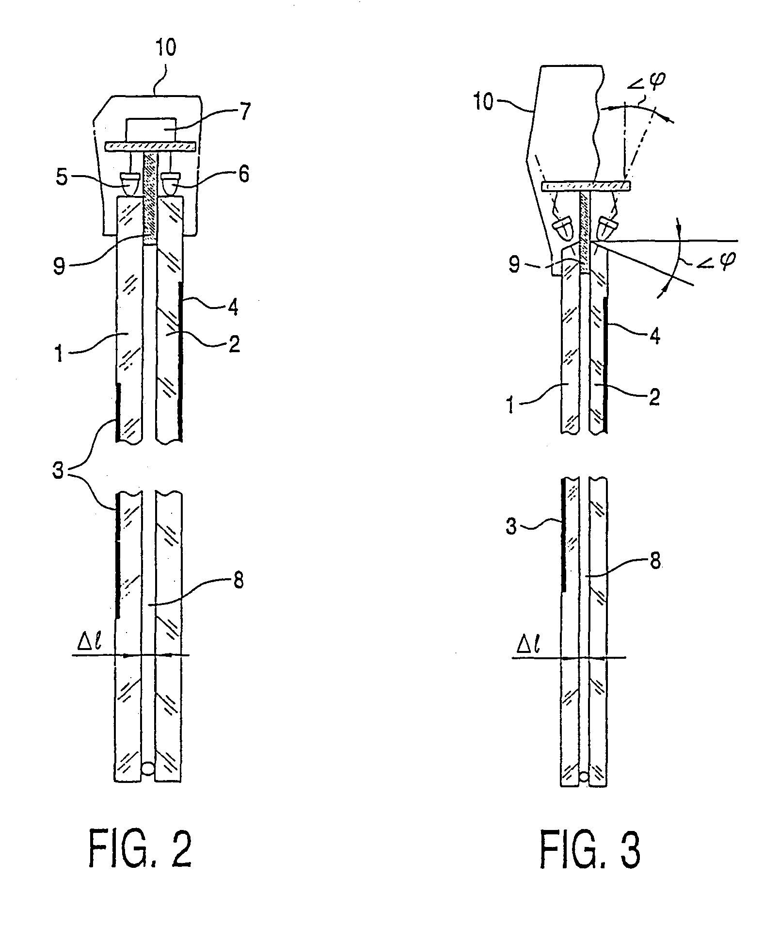
[0012]The above object is achieved by a data display device as mentioned above, characterized in that the device also includes: at least one additional light-guide element made of an optically transparent material having at least two polished surfaces faced to one another, whereby at least one surface contains at least one gravure forming a diffuse-reflective character, and at least one additional light source arranged to illuminate said diffuse-reflective character, whereby said light-guide elements being mounted at a distance one from each another such that the minimum distance between the guide-elements exceeds the red-light wavelength and each light source is being optically isolated from each another. Essential for the claimed device are the characterizing features namely introduction of extra light-guide elements conforming to the existing light-guide element and having (air) gaps between them, in combination with the use of light sources—preferably point light sources such as Light Emitting Diodes (LED's) and lasers—united in light-isolated groups according to the number of light-guide elements. So, the feature of conformity (similarity) of two and more light-guide elements generally dictates the use of curvilinear shapes within a single design. The presence of an air gap between light-guide elements guarantees a minor reflection of light-beams from the polished surfaces. (N. S. Kapany, Fiber Optics, Principles and Applications, Academic Press. N.Y. 1967) With curvilinear elements as well as with rectilinear elements, point light sources ensure highly effective illumination and provide a possibility to follow a curvilinear outline of any number of light-guide elements in a unit. Light isolation of groups of point light sources makes it possible to illuminate each light-guide element separately. Using the claimed device for demonstration of information makes it possible to achieve a benefit consisting in expansion of the device applications, in increasing the information capacity, in reducing power input and in adding to the failure operating time through the improvement of the device. There is a casual relationship between the benefit of the invention and distinguishing features of the claimed device as the feature of introduction of additional light-guide elements in combination with the feature of introduction of conforming light-guide elements ensures expansion of the device applications and provides an increase in information capacity of the claimed device due to making additional diffuse-reflective characters on the surfaces.
[0013]A mentioned above consists each light source of multiple point light sources. Small-sized point light sources used for illumination of diffuse-reflective characters make it possible to improve effectiveness of filling-in the internal volume of a light-guide element with light beams. Due to their size some few point light sources may be placed on small areas thus providing multiprogramming modes of their “on-off” action, which is effected in the device by means of the electronic programmed control unit. Accordingly, the distinguishing features of the claimed device are necessary and sufficient to achieve the benefit of the invention, with the said features being under legal protection in full measure.
[0014]Light-guide elements on the point source side are made curvilinear, with the curvature radius being no more than the thickness of the light-guide element. This is an additional feature specifying the structural possibility to widen the angle of the radiation directivity diagram of the point light sources. This feature is aimed at improving the effectiveness in illuminating a light-guide element while using highly intensive narrow-beam light sources. Restriction to the curvature radius is a structural parameter. All the light-guide elements of the claimed device are made curvilinear. This is an additional feature specifying conformity (similarity) of light-guide elements that may be united in a single light-guide unit.

Problems solved by technology

A principal drawback of the known device lies in its structural imperfection as dictated by a traditional approach to an information screen thought of as a plane.
Such an approach comes into an apparent conflict with laws of light conductivity.
Another drawback of the device known from the art is associated with the use of luminescent light sources in “Acryllights”, above all in the form of tubes that are matched in length to the size of the light-guide plate.
Diameters of the tube luminescent light sources exceed the thickness of the light-guide element, so the effectiveness of the lighting of diffuse-reflecting characters is low.
Also, the size of luminescent light sources prevents some light-guide elements from being used in one unit.

Method used


Image

  • Data display device
  • Data display device
  • Data display device

Examples


Embodiment Construction

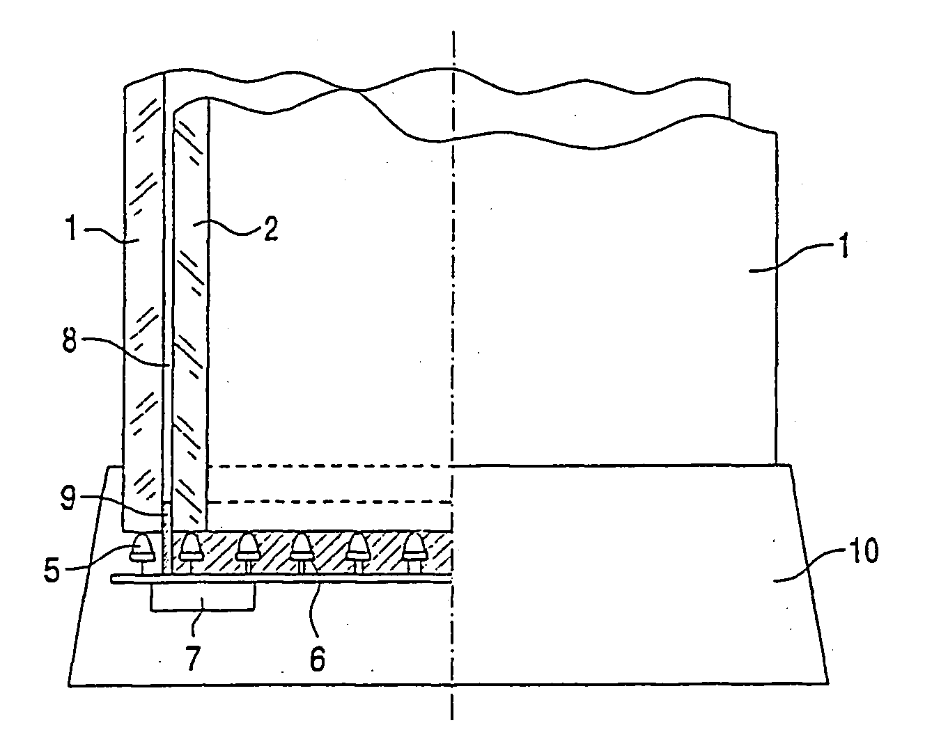
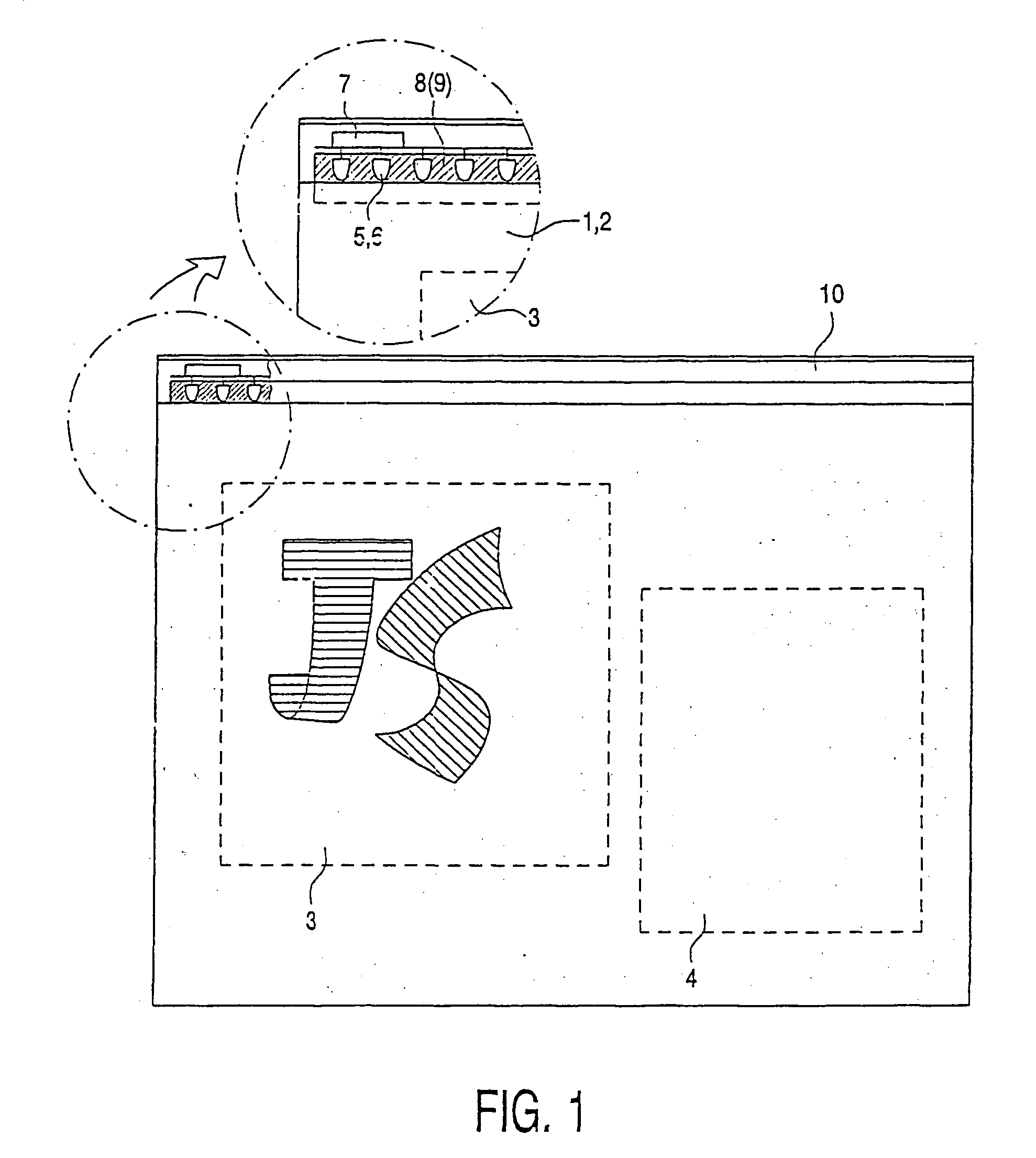
[0048]FIG. 1 is a design of the data display device comprising at least two light-guide elements 1, 2 having polished surfaces. For an optical material, acrylic “organic” glass may be used. Engraved on the wide surface of the light-guide element 1, on one or two sides, there are provided engraved diffuse-reflective characters (signs, litters, pictures) 3 to form in the aggregate an information unit, e.g. a logotype of a trade-mark. The wide polished surface of the light-guide element 2 is also furnished with diffuse-reflective characters located in the zone 4. Structurally, the device in FIGS. 1 and 2 is provided with light-guide plates 1 and 2 of a rectangular shape, with point radiators being mounted on their narrow polished sides to illuminate the characters 3 while the zone 4 being furnished with characters on the plates 1 and 2, respectively. As is seen in FIGS. 1 and 2, the point radiators are provided with electric power-supply units to choose modes of ‘on-off’ action of the ...


PUM


Abstract

A data display device including a light-guide element made of an optically transparent material having at least two polished surfaces faced to one another, whereby at least one surface contains at least one gravure forming a diffuse-reflective character, and a light source arranged close to the light-guide element to illuminate said character.

Description

BACKGROUND OF THE INVENTION[0001]1. Field of the Invention[0002]The invention relates to a data display device including a light-guide element made of an optically transparent material having at least two polished surfaces faced to one another, whereby at least one surface contains at least one gravure forming a diffuse-reflective character, and a light source arranged close to the light-guide element to illuminate said character.[0003]2. Description of the Prior Art[0004]This invention is in the class of illumination engineering as well as in the class of advertising-information technologies. The claimed device may find its application in architecture as interior lamps doubling for functions of decorative luminaries.[0005]The principle of action of the claimed device is based on well-known laws of geometric optics. Among these laws are:[0006]1) the law of conductivity of light beams in an optically transparent media having a refractive index n1>1.0, these media being in contact ...

Claims


Application Information

Patent Timeline
Patent Type & Authority Patents(United States)
IPC IPC(8): F21V7/04F21V8/00G09F13/18G02B6/00G09F13/00G09F13/32
CPCG02B6/0001G02B6/0028G02B6/0068G02B6/0076G02B6/0083G02B6/002G02B6/0036G02B6/006
Inventor BURTSEV, VLADIMIR NIKOLAYEVICHBURTSEV, VALERY NIKOLAYEVICHSTETSENKO, OLEKSANDR PETROVICH
Owner ESTRAKON
Learn More