Loaded weight measurement method and loaded weight measurement device for dump truck

a technology for dump trucks and loading weights, applied in the direction of analogue processes, instruments, transportation items, etc., can solve the problems of difficult to accurately detect the load applied to the central wheels, the conventional technology cannot be applied directly to dump trucks having respective left and right-hand and the difficulty of applying directly to dump trucks having two pairs of wheels in either the front section or the rear section

Active Publication Date: 2007-07-24
KOMATSU LTD
View PDF4 Cites 13 Cited by
  • Summary
  • Abstract
  • Description
  • Claims
  • Application Information

AI Technical Summary

Benefits of technology

[0016]According to the present invention, in a dump truck comprising first vehicle wheels and second vehicle wheels which are coupled by equalizer bars, it is possible to calculate the loaded weight by using first and second load detecting means only, without provided load detecting means in all of the suspension devices. Therefore, it is possible to detect the loaded weight accurately by means of a small number of detecting means.

Problems solved by technology

However, this conventional technology can only be applied to a dump truck having respective left and right-hand pairs of wheels in the front and rear portions of the vehicle body.
Therefore, it is difficult to apply directly to a dump truck having two pairs of wheels in either the front section or rear section, as in the case of an articulated dump truck, for instance.
Here, for example, if the front wheels and the rear wheels are supported respectively by suspension cylinders, and the central wheels are supported by springs, then it is difficult to detect the load applied to the central wheels, accurately.
However, this method produces significant error in the measurement of the loaded weight.
However, suspension cylinders are expensive compared to springs, and since pressure sensors must also be provided, the manufacturing costs of the dump truck increase.

Method used


Image

  • Loaded weight measurement method and loaded weight measurement device for dump truck
  • Loaded weight measurement method and loaded weight measurement device for dump truck
  • Loaded weight measurement method and loaded weight measurement device for dump truck

Examples


first embodiment

[0034

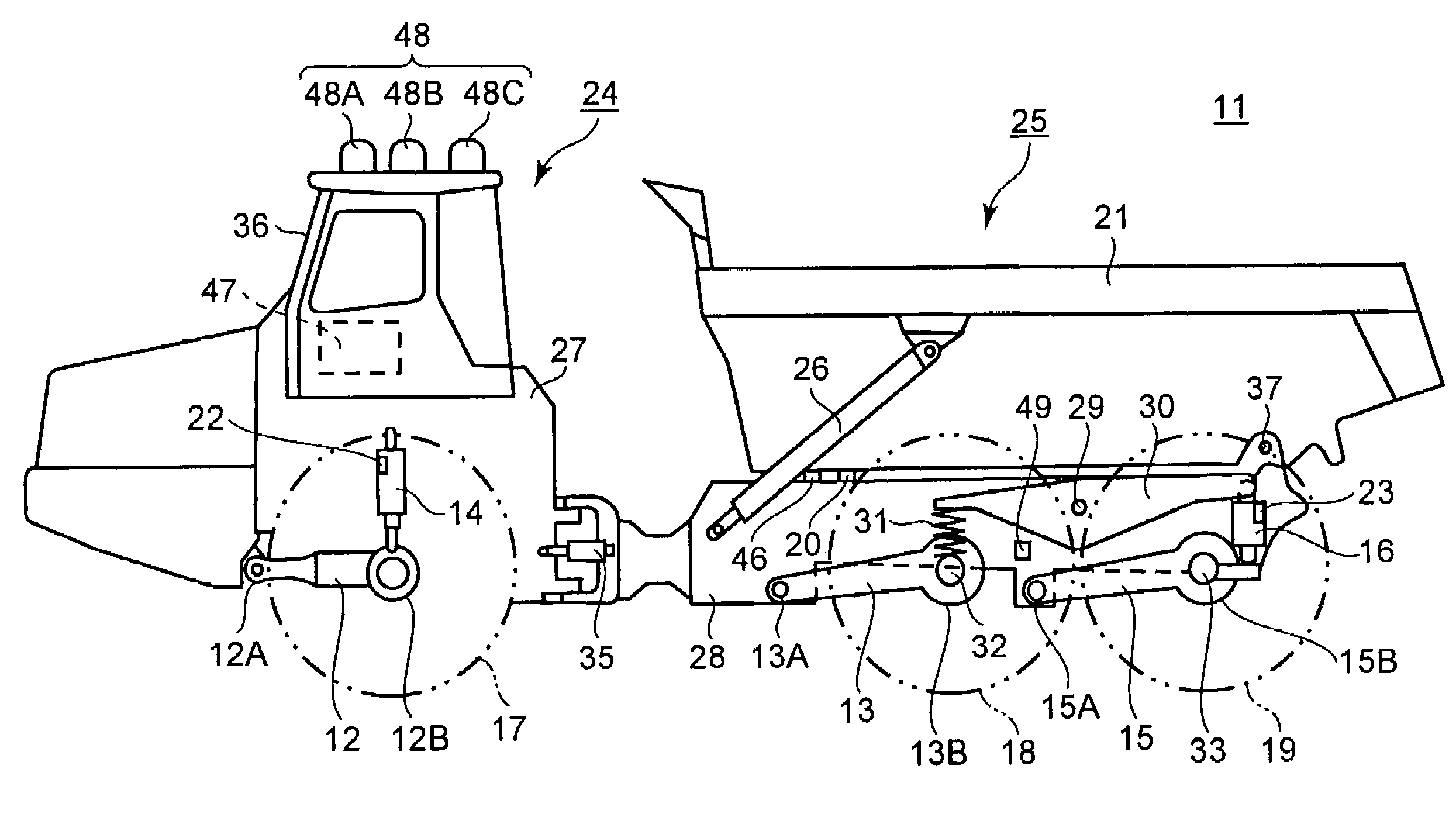
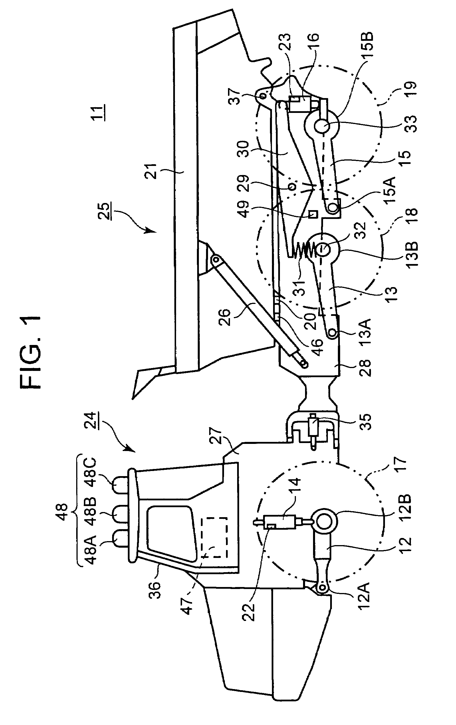
[0035]A first embodiment of the present invention will be described with reference to FIG. 1–FIG. 8. FIG. 1 is a side view of an articulated type dump truck 11.

[0036]As shown in FIG. 1, the dump truck 11 comprises a front vehicle body 24 disposed on the front side and a rear vehicle body 25 disposed on the rear side. The front vehicle body 24 is supported by means of a front frame 27 and the rear vehicle body 25 is supported by means of a rear frame 28. The rear frame 28 is coupled bendably and swingably with respect to the front frame 27. An driver's cabin 36 is mounted on the front frame 27.

[0037]A left and right-hand pair of steering cylinders 35, 35 are provided spanning between the front frame 27 and the rear frame 28. By respectively extending or contracting the steering cylinders 35, 35, the rear frame 28 can be made to turn with respect to the front frame 27, and hence a steering operation can be performed.

[0038]A vessel 21 for loading a cargo, such as sand, for example...

second embodiment

[0111

[0112]Next, a second embodiment will be described on the basis of FIG. 9–FIG. 11. In this embodiment, as described below, it is previously judged whether or not conditions for accurately measuring the loaded weight have been established, and if accurate measurement cannot be performed, then a cautionary warning is issued to the operator, or the like. Furthermore, in this embodiment, automatic diagnosis is carried out on the basis of the loaded weight of the dump truck 11, in order to tell whether or not the truck is situated in an accurate measurement environment.

[0113]Firstly, a general work procedure of the dump truck 11 will be described. FIG. 9 shows a work procedure of the dump truck 11. The dump truck 11 halts at a loading point, with the empty vessel 21 seated on the rear frame 28 (S21). The loading operator loads a cargo to be conveyed, such as sand, into the vessel 21, by means of a hydraulic shovel, wheel loader, or the like (S22).

[0114]When the loaded weight G has be...

third embodiment

[0143

[0144]Next, a third embodiment will be described on the basis of FIG. 12–FIG. 14. In this embodiment, as described hereinafter, a limit switch 50 is used in order to detect whether or not the equalizer bar 30 is abutted against the stopper 51.

[0145]In the second embodiment described above, it is judged whether or not the equalizer bar 30 is abutting against the stopper 51 when the dump truck 11 is halted in an empty state. However, the equalizer bar 30 may also become abutted against a stopper 51 in other circumstances, for instance, during loading, during travel or during unloading, and not only when the dump truck 11 is halted in an empty state. In these circumstances also, it is possible that error may occur in the measurement values for the loaded weight due to similar reasons to those described above.

[0146]In this embodiment, limit switches 50 are provided in order to detect whether or not the equalizer bar 30 is abutted against a stopper 51, as shown in FIG. 12. The limit...


PUM


Abstract

To measure the loaded weight of a dump truck, accurately and inexpensively. In a dump truck comprising a set of equalizer bars respectively provided rotatably on the left and right-hand sides of a vehicle body; first vehicle wheels supported respectively by way of first suspension devices on one side of each equalizer bar; second vehicle wheels supported respectively by way of second suspension devices on the other side of each equalizer bar; and third vehicle wheels provided respectively on the left and right-hand sides of the vehicle body separately from the equalizer bars, and being supported respectively by way of third suspension devices; a first load applied to the second suspension device is detected; a second load applied to the third suspension device is detected; the angle of inclination of the vehicle body is detected; and a loaded weight is calculated on the basis of the first and second loads, and the angle of inclination.

Description

BACKGROUND OF THE INVENTION[0001]1. Field of the Invention[0002]The present invention relates to a loaded weight measurement method and loaded weight measurement device for a dump truck.[0003]2. Description of the Related Art[0004]A method is known in the prior art (Japanese Patent Laid-open No. 61-34425) in which the weight of cargo is measured by detecting the load applied respectively to the front wheels and the rear wheels of a dump truck and correcting these detected loads on the basis of the angle of inclination of the vehicle and the center of gravity of the vehicle.[0005]According to the prior art technology described in Japanese Patent Laid-open No. 61-34425, it is possible to determine the weight of a cargo simply by detecting the loads applied respectively to the front wheels and rear wheels. However, this conventional technology can only be applied to a dump truck having respective left and right-hand pairs of wheels in the front and rear portions of the vehicle body. Th...

Claims


Application Information

Patent Timeline
Patent Type & Authority Patents(United States)
IPC IPC(8): G01G19/08G01G23/00
CPCB60G5/04B60G17/019G01G19/08G01G23/002B60G2202/154B60G2204/112B60G2300/0262B60G2400/0511B60G2400/0512B60G2400/5122B60G2400/61B60G2400/63B60G2800/702
Inventor TAKEDA, SHUMATSUDA, KAZUO
Owner KOMATSU LTD
Why Eureka
Try Eureka