Optical moisture sensor and method of making the same

a moisture sensor and optical technology, applied in the direction of optical elements, instruments, investigating moving fluids/granular solids, etc., can solve the problems of adversely affecting the parallelism of internally refracted rays, not being practical for soil, air space needs, etc., and not being practicable for soil

Inactive Publication Date: 2007-07-24
TORO CO THE
View PDF9 Cites 5 Cited by
  • Summary
  • Abstract
  • Description
  • Claims
  • Application Information

AI Technical Summary

Problems solved by technology

The above-described prior art construction is not, however, practical for soil moisture sensors because the presence of particulates in soil requires using the maximum available surface area of the ellipsoidal body as a reflection surface, so as to average the moisture effects over as large a surface of the sensor body as possible.
A disadvantage of the sensor shown in the above-cited copending application in cold and moist environments is the fact that an air space needs to exist between the light source or photosensor and the internal refracting surface.
In either event, these conditions may adversely affect the parallelism of the internally refracted rays and may require special manufacturing precautions.
This does, however, cause several other problems.
Consequently, the sensitivity of such a sensor is substantially compromised.
Another problem arises in the manufacture of moisture sensors of the type described due to the fact that the light source and photosensor must be maintained in exact alignment with the foci of the ellipsoid during manufacture.
Also, the difference in coefficients of expansion between the body material and the circuit board on which the sensor's optical and electronic components are typically mounted can cause minute cracks adjacent the board into which moisture can migrate.

Method used


Image

  • Optical moisture sensor and method of making the same
  • Optical moisture sensor and method of making the same
  • Optical moisture sensor and method of making the same

Examples


Embodiment Construction

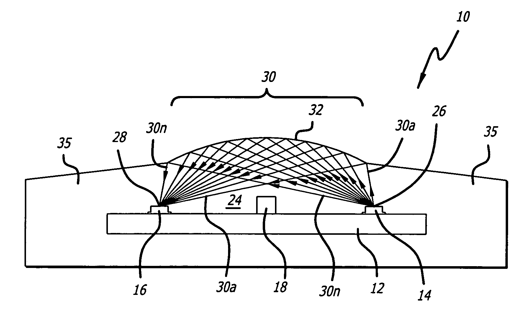
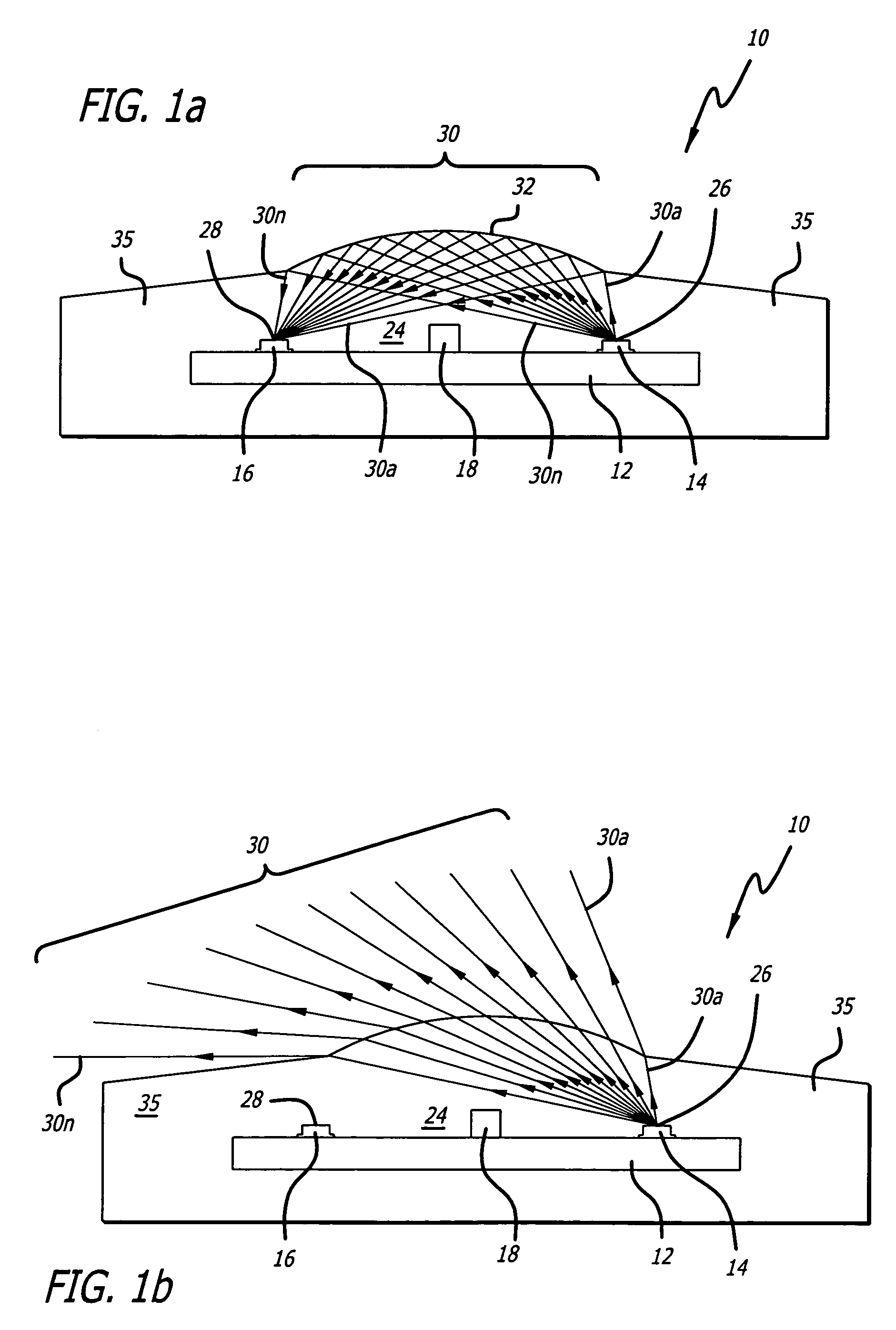
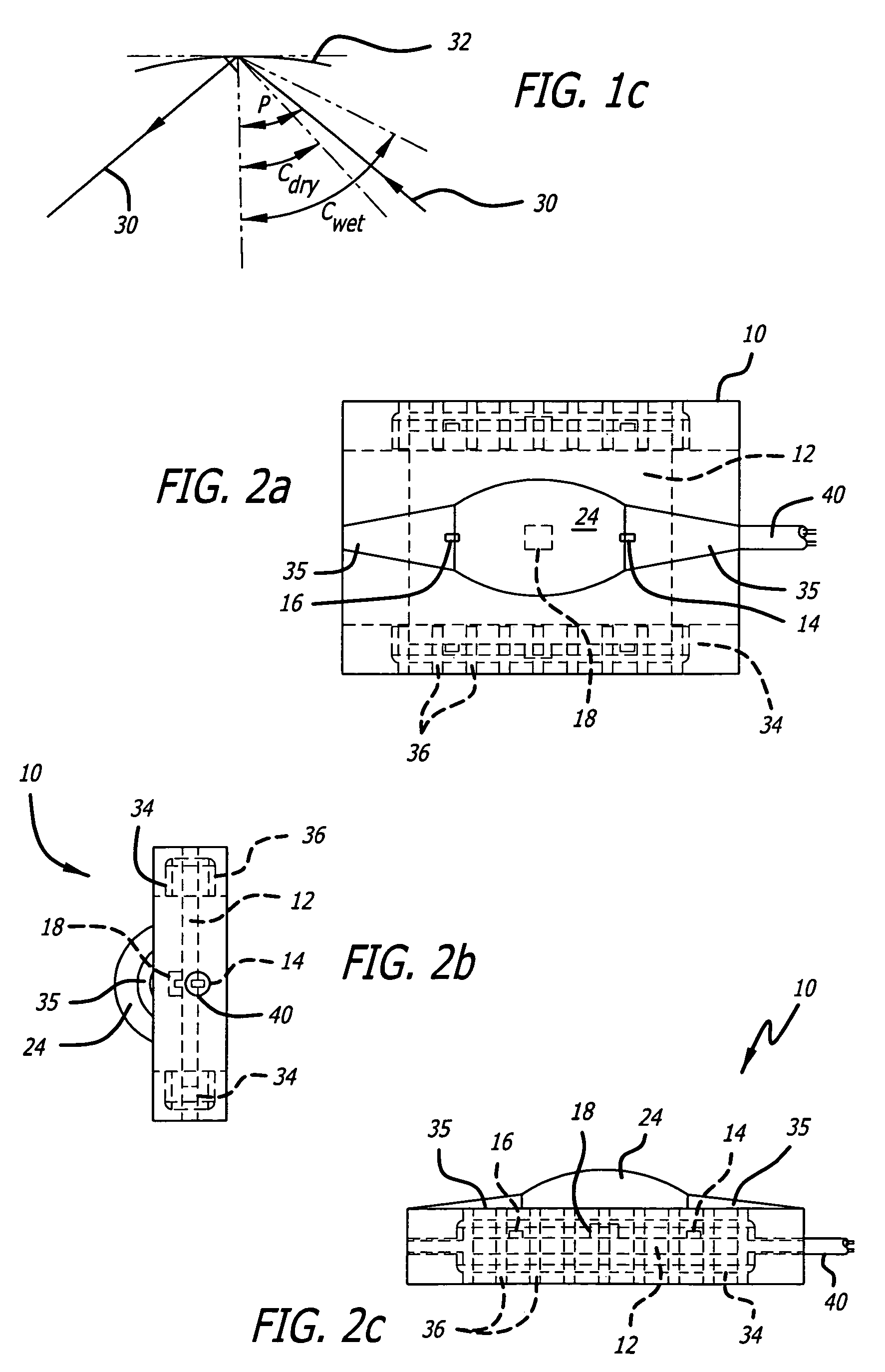
[0020]FIGS. 1a and 1b illustrate the functioning of the invention. The sensor 10 consists of a circuit board 12 carrying a light source such as, e.g., an infrared emitting diode (IRED) 14, a light sensing device such as, e.g., a photosensor 16, and a component package 18. The components of the package 18 may, for example, include transformers, capacitors and / or resistors, or other components suitable for causing the IRED 14 to produce appropriate illumination and to cause the illumination received by the photosensor 16 to be translated into usable signals. In accordance with the invention, the package 18 is positioned on the circuit board 12 between the IRED 14 and the photosensor 16. The package 18 is opaque and taller than the elevation of the IRED 14 and photosensor 16 with respect to the circuit board 12, so as to shade the photosensor 16 from direct illumination by the IRED 14.

[0021]An ellipsoidal body 24 of a transparent plastic such as cyclic olefin copolymer (COC) or acrylic...


PUM

PropertyMeasurementUnit
angleaaaaaaaaaa
angleaaaaaaaaaa
angleaaaaaaaaaa

Abstract

A soil moisture sensor uses a non-collimated light source and a photosensor, respectively, mounted at the foci of a transparent ellipsoidal plastic body. The dimensions of the body are such that emitted light rays are internally reflected toward the photosensor at the surface of the ellipsoid if the surface is dry, but refracted outwardly of the body when the surface is wet. The amount of light reflected onto the photosensor is thus a measure of the amount of moisture at the surface of the sensor. Direct illumination of the photosensor by the light source is prevented either by interposing opaque electronic components between them on a circuit board, or by taking advantage of light source characteristics to minimize the amount of transmitted light. If a circuit board is used, it is completely encapsulated against moisture penetration by fixing it in a carrier and molding the body around and onto the carrier to form a monolithic unit with the carrier and circuit board.

Description

RELATED APPLICATIONS[0001]This application claims priority to U.S. Provisional Application Ser. No. 60 / 605,178 filed Aug. 27, 2004 entitled Optical Moisture Sensor and Method of Making the Same and is hereby incorporated by reference.FIELD OF THE INVENTION[0002]This invention relates to optical moisture sensors for irrigation systems, and more particularly to a soil moisture sensor using a solid, transparent ellipsoidal body with a non-collimated light source embedded at one of its foci to reflect light toward a photosensor embedded at the other focus of the body if the soil contacting the surface of the body is dry, or to refract it outwardly of the body if the soil is wet.BACKGROUND OF THE INVENTION[0003]Optical sensors for determining the moisture content of the soil in an irrigation system are well known. They usually take the form of a prism or similar structure, in which a light beam projected into the prism is internally reflected toward a photosensor such as a photodiode or ...

Claims


Application Information

Patent Timeline
Patent Type & Authority Patents(United States)
IPC IPC(8): G01N21/01
CPCA01G25/167G01N21/552
Inventor ZIMMERMAN, JAMES
Owner TORO CO THE
Why Eureka
Try Eureka