[0017] A protective coating is disclosed for strain gauges that are or can be installed on a deformable body of a force-measuring cell which on the one hand prevents moisture from entering and on the other hand avoids or at least significantly reduces bypass forces.
[0018] Exemplary embodiments use the excellent barrier properties that are found in the predominantly
inorganic materials and, by using very thin barrier coatings, achieves a reduction of the very
high stiffness associated with the thick inorganic coatings that are used under the existing state of the art. This occurs in a plurality of
layers with an alternating sequence of thin barrier layers and thin
polymer layers.
Polymer layers, although they have only a moderate
barrier effect and therefore can often not provide adequate moisture protection by themselves, have the
advantage of a considerably lower stiffness. When used in combination with thin, predominantly inorganic barrier layers, the
polymer layers are a suitable means of reducing the overall stiffness of a coating with a plurality of layers. This concept preserves the advantages mentioned at the outset which are associated with the low stiffness of a
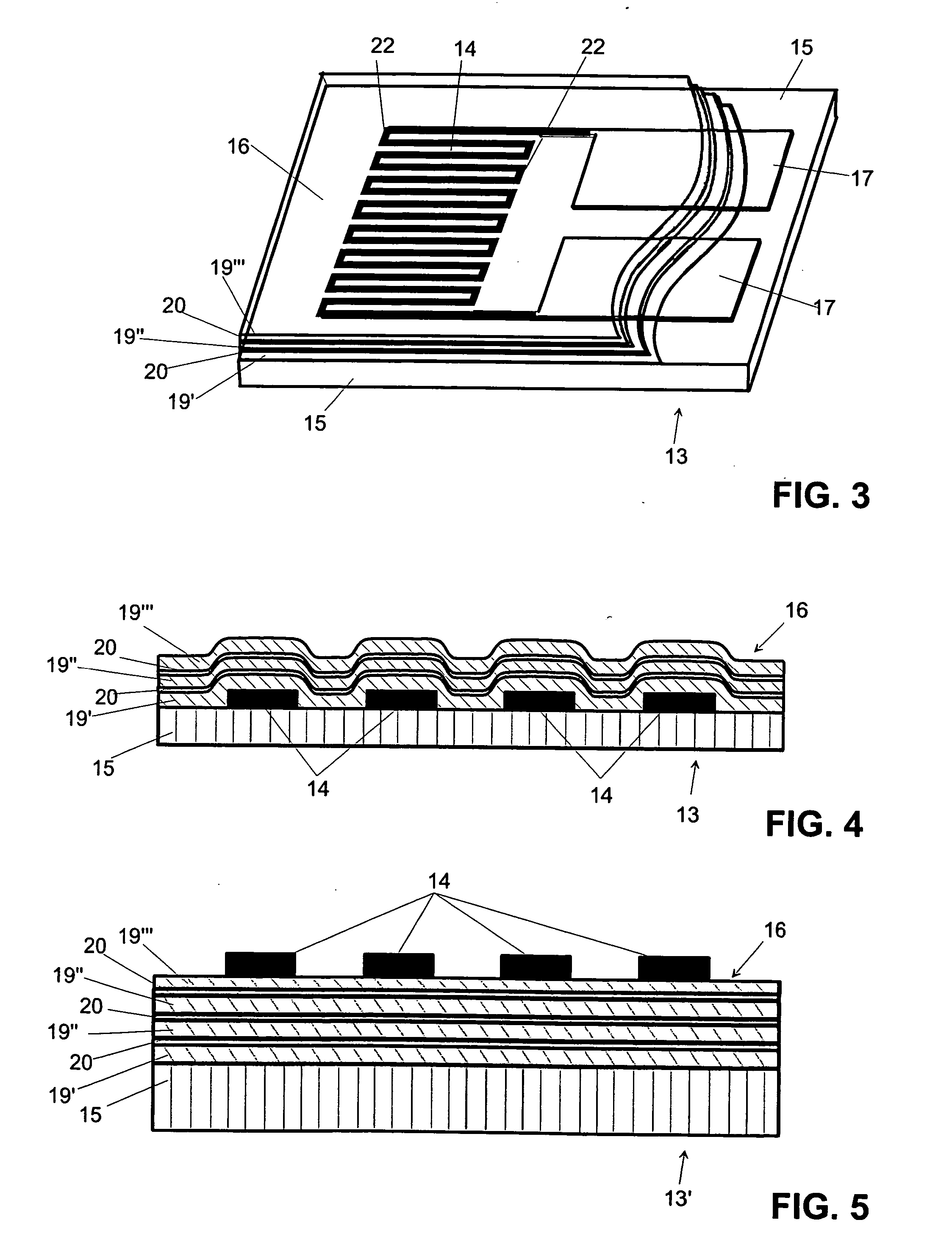
polymer substrate material for a strain gauge. With the very thin barrier layers in the multilayered coating, the drawback of bypass forces described above is avoided to the largest extent possible. A predominantly inorganic either electrically insulating or metallic layer as a barrier layer with a thickness of about 5 nanometer (nm) to 200 nm, in individual cases up to 500 nm, preferably however 10 nm to 50 nm, has a comparatively low stiffness of about the same
order of magnitude as the polymer layers adjacent to the barrier layer.
[0019] The so-called pinholes that are known from the coating technology for thin films, i.e., microscopically small holes or also fissures in the barrier layers, are likewise reduced by the polymer layers in the multilayered coating. The size and number of the pin holes in a barrier layer depend on the roughness and flatness of the underlying base surface besides many other coating parameters including the coating material itself, but they depend only to a small extent on the thickness of the coating layer. The polymer layers have a
smoothing effect which to a large extent prevents the occurrence of pin holes or at least diminishes their influence. The sequence of thin barrier layers with a thickness of about 5 nm to 200 nm, in individual cases up to 500 nm, preferably however 10 nm to 50 nm, and polymer layers with a thickness of 50 nm up to about 1500 nm provides first of all a certain sealing effect for the aforementioned pinholes and secondly has the effect that the pinholes are in staggered positions from one barrier layer to the next, whereby the moisture is prevented from breaking through at such weakened locations because the water and
solvent molecules are held up by a labyrinth-like hurdle. Thus, an effective moisture protection can be achieved for strain gauges without producing a harmful effect on the result of the measurement.
[0020] Exemplary embodiments remove another
disadvantage associated with thick inorganic barrier layers, i.e., the risk that the coating will peel off, which is referred to as
delamination. The cause of delamination lies in the considerable mechanical stresses which occur at the transition from the surface of the strain gauge to the barrier layer and which are due to the
high stiffness of a comparatively thick barrier layer. Using thin barrier layers alternating with thin polymer layers in accordance with exemplary embodiments of the invention gives a very high stability to the coating with regard to the undesirable peeling off a barrier layer from its underlying base surface.
[0021] When used in accordance with exemplary embodiments of the invention as overall thin multilayered protective coatings and with a sequence of thin primarily inorganic barrier layers and surface-
smoothing polymer layers, the multilayered coatings can cover a strain gauge that has already been installed on a force-measuring cell or a strain-gauge that is designed for installation on a force-measuring cell. A purpose of the multilayered coatings is to minimize the negative effects on the measurement performance of such a force-measuring cell which would otherwise occur because of
moisture penetration, and at the same time to largely prevent bypass forces which occur with thick barrier layers or barrier foils and which falsify the very same measuring performance that is to be secured by the barrier layers or foils.
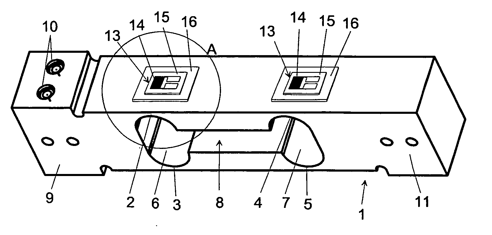
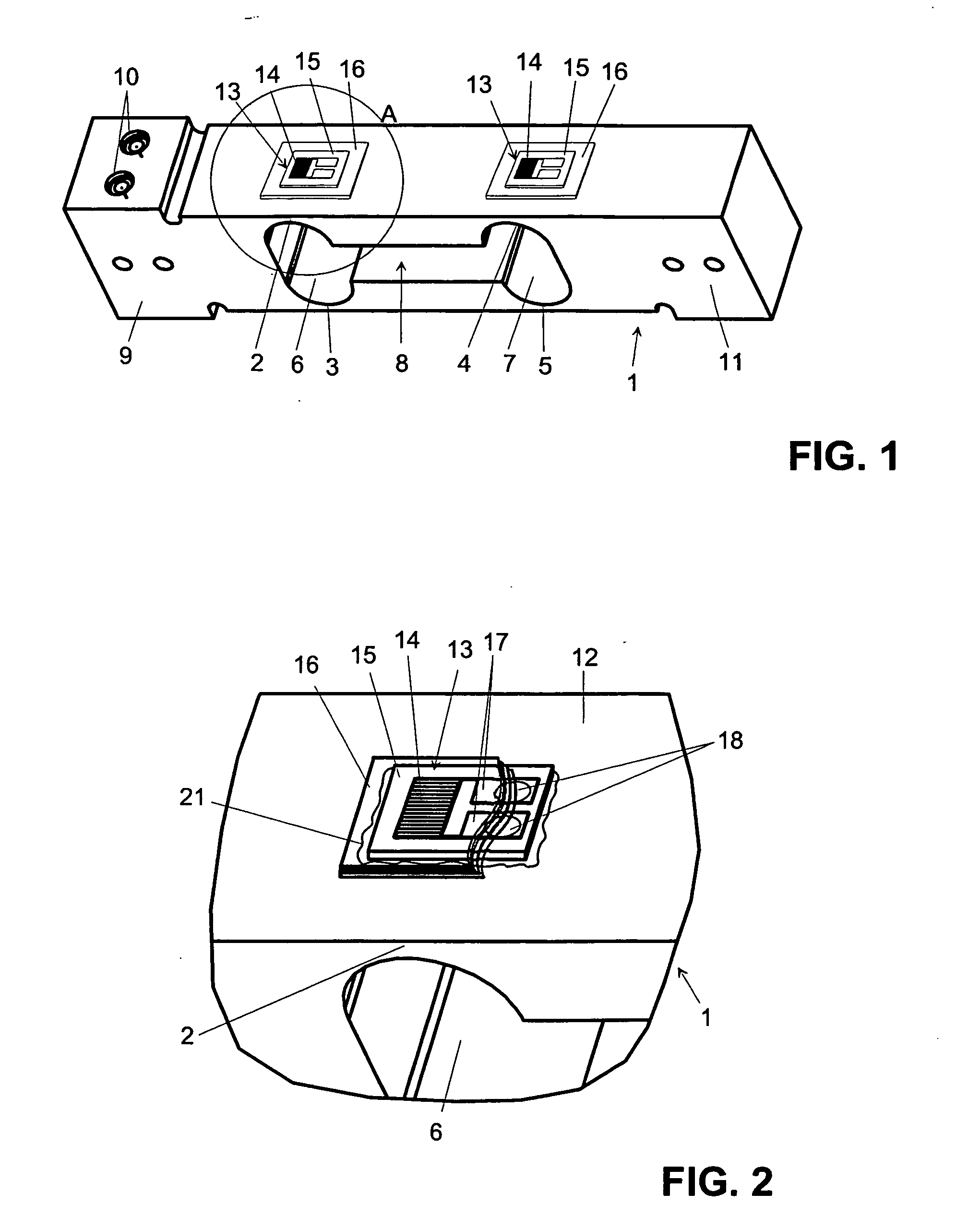
[0022] By applying the concepts of the foregoing description, the sensitivity of force-measuring cells with one or more strain gauges that are installed as
transducer elements on a deformable body is strongly improved so that for example the resolution of weighing scales equipped with these force-measuring transducers can be raised to a level which has heretofore been reached only with balances that work according to the principle of electromagnetic force compensation.

