Transflective electrophoretic display and manufacturing method thereof

a technology of transflective electrophoretic display and manufacturing method, which is applied in the direction of optics, static indicating devices, instruments, etc., can solve the problems of insensitive electrophoretic display, large power consumption of transmittance electrophoretic display devices, and inability to show images, etc., to improve image contrast, power consumption reduction, and enhance overall brightness

Inactive Publication Date: 2007-07-24
IND TECH RES INST
View PDF5 Cites 27 Cited by
  • Summary
  • Abstract
  • Description
  • Claims
  • Application Information

AI Technical Summary

Benefits of technology

[0017]An objective of the present invention is to provide a transflective electrophoretic display structure to use both ambient light and backlight as light sources. The display structure of the present invention not only enhances the overall brightness but also illuminates the display area in darkness. The backlight module of the present invention can be adjusted according to the intensity of ambient light so that the power consumption is reduced and the contrast of images is increased. Moreover, since the present invention adopts a simple driving mechanism, the design and manufacturing process can be simplified.

Problems solved by technology

In addition, the electrophoretic display is insensitive to spacing variation of substrates and possesses bistability.
However, this type of display devices cannot show images when ambient light is insufficient or doesn't exist.
Thus, the power consumption of transmittance electrophoretic display devices is so large that made this display not suitable for mobile device applications.
However, the separating walls 109 may leak light.
Hence, this display device doesn't have a high display quality.
Hence, this display device is complicated in design and has a difficult manufacturing process.

Method used


Image

  • Transflective electrophoretic display and manufacturing method thereof
  • Transflective electrophoretic display and manufacturing method thereof
  • Transflective electrophoretic display and manufacturing method thereof

Examples


first embodiment

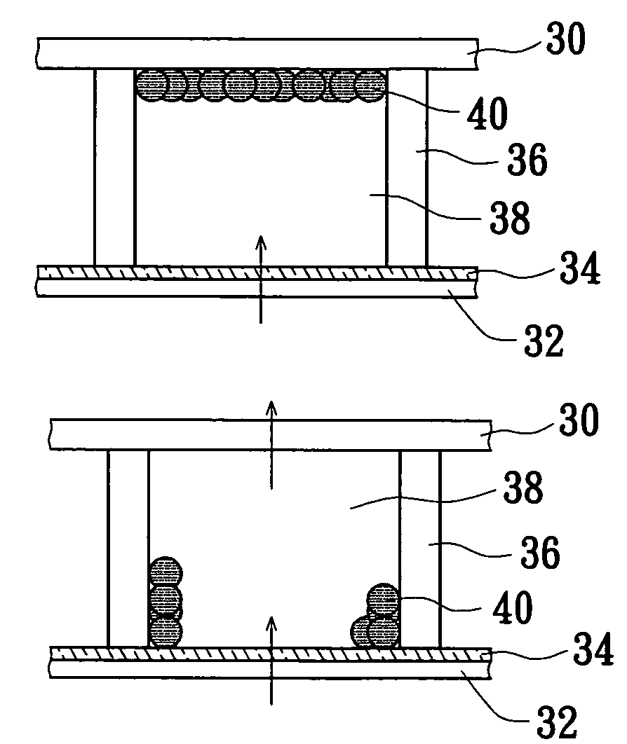
[0050]Reference is made to FIG. 4A, which shows a transflective electrophoretic display device having a display cell that displays a black color in accordance with the present invention. In this embodiment, the color of the pigment particles is black. When light emitted from the backlight module passes through the bottom substrate 32 and the transflective film 34 to enter the display rooms 38, the light is reflected by the separating walls 36, which are opaque in this embodiment, and is passed toward the top substrate 30. As shown in FIG. 4A, since the light is completely absorbed by the black particles distributed along and covering the lower surface of the top substrate 30, the backlight does not pass through the display cell. In this embodiment, the black particles can also be distributed along and covering the upper surface of the bottom substrate 32 (not shown). In addition, since the black particles cover the top or bottom substrate, ambient light is also absorbed by the black...

second embodiment

[0052]Reference is made to FIG. 5A, which shows a transflective electrophoretic display device having a display cell that displays a white color in accordance with the present invention. The display cell includes a transparent top substrate 30 and a bottom substrate 32. Separating walls 36 are disposed between the top and bottom substrates. Anisotropic reflective plates 42 are disposed in the top substrate 30 above the separating walls 36. Both the transparent top substrate 30 and the bottom substrate 32 have in-plane electrodes for providing transverse electric fields. The pigment particles 40 are distributed near the lower ends of the separating walls 36. A transflective film 34 is provided on the bottom substrate 32.

[0053]In this embodiment, the separating walls 36 are transparent and light emitted from a light source disposed beneath the display room 38 can pass through the transflective film 34 and the separating walls 36. When the light reaches the anisotropic reflective plate...

third embodiment

[0061]Reference is made to FIG. 6A, which shows a color transflective electrophoretic display device having a color display cell that displays a white color in accordance with the present invention. First, light emitted from the backlight module beneath the bottom substrate 502 passes through the transflective film 512 and enters the display rooms formed between the separating walls 52. Due to the color display solvents 51, 53, and 55, red, green and blue lights are produced. In addition, the charged pigment particles in the color display solvents 51, 53, and 55 drift to the lower ends of the separating walls 52 because a predetermined electric field is provided. Thus, the red, green and blue lights can pass through the top substrate 501 and are mixed together to form white light.

[0062]The color display cell can also produce color light by reflection of ambient light. When ambient light passes through the color display solvent 51, 53, or 55 and is reflected back by the transflective...


PUM

PropertyMeasurementUnit
transmittanceaaaaaaaaaa
reflectanceaaaaaaaaaa
transparentaaaaaaaaaa

Abstract

A transflective electrophoretic display and a method for manufacturing the same are proposed. The transflective electrophoretic display including a top substrate and a bottom substrate, multiple separating walls disposed between the top and bottom substrates, a transflective film, and an electrophoretic display medium, can be designed to display colors by using multicolor electrophoretic display media or color filters. The display can be viewed with or without ambient light by adopting a backlight module, as well as to improve the overall display quality.

Description

BACKGROUND OF THE INVENTION[0001]1. Field of the Invention[0002]The present invention is related to a transflective electrophoretic display and a method for manufacturing the same, and more particularly, to a display structure that changes the behavior of charged pigment particles via adjustment of an electric field and a method for manufacturing the display structure.[0003]2. Description of Related Art[0004]An electrophoretic display adjusts an electric field to control the distribution of charged particles to change its display regions' reflectance for ambient light and thus to display images. The electrophoretic display is flexible and the images shown on the electrophoretic display can be viewed by using ambient light. Furthermore, the electrophoretic display can be made by using a roll-to-roll manufacturing procedure. It is thus convenient for mass production and its cost can also be reduced. Moreover, the visual angle of the electrophoretic display is unlimited. Hence, the ima...

Claims


Application Information

Patent Timeline
Patent Type & Authority Patents(United States)
IPC IPC(8): G02B26/00G09G3/34G02F1/167G02F1/1677G02F1/1679
CPCG02F1/167G09G3/344G02F2203/09G09G2300/0456G02F1/1679G02F1/1677
Inventor DING, JAU-MINLIAO, CHI-CHANGJENG, SHIE-CHANG
Owner IND TECH RES INST
Why Eureka
Try Eureka