Direct relative motion measurement for vibration induced noise and drift cancellation

a technology of relative motion and noise cancellation, applied in the field of surface analysis, can solve problems such as more difficult correction and thus limited

Inactive Publication Date: 2007-07-24
KLA TENCOR TECH CORP
View PDF5 Cites 29 Cited by
  • Summary
  • Abstract
  • Description
  • Claims
  • Application Information

AI Technical Summary

Benefits of technology

[0033]Alternatively, in outside-the-loop compensation, the displacement signal S3 may be subtracted electronically, (e.g., in a digital or analog device) from the adjustment signal S2 and the difference (S2−S3) may be used to image the sample surface. The subtraction may take place in conjunction with adjustment by the compensation mechanism 218 or independent of it. For example, as depicted in FIGS. 3A–3C, the displacement signal S3 may be s

Problems solved by technology

Unfortunately, although vibrations of the microscope table have an effect on the distance between the table and probe tip, the displacem

Method used


Image

  • Direct relative motion measurement for vibration induced noise and drift cancellation
  • Direct relative motion measurement for vibration induced noise and drift cancellation
  • Direct relative motion measurement for vibration induced noise and drift cancellation

Examples


Embodiment Construction

[0014]Although the following detailed description contains many specific details for the purposes of illustration, anyone of ordinary skill in the art will appreciate that many variations and alterations to the following details are within the scope of the invention. Accordingly, the exemplary embodiments of the invention described below are set forth without any loss of generality to, and without imposing limitations upon, the claimed invention.

INTRODUCTION

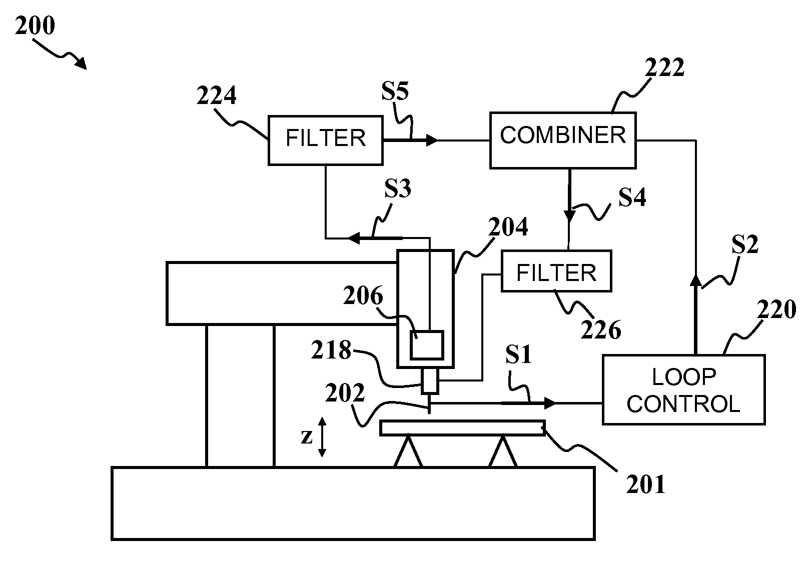
[0015]In a scanning probe surface analysis system, the signal from the probe depends on the relative distance between the probe and the surface under analysis. The probe is usually mounted to a scanning head that is, in turn, mounted to a microscope table through supports that suspend the scanning head over the sample. In a system like that described in U.S. Pat. No. 6,308,557, the vibration sensor is located on the microscope table. Unfortunately, although vibrations of the microscope table have an effect on the distance between...


PUM


Abstract

A surface analysis apparatus and a method for compensating for mechanical vibrations and drifts in a surface analysis instrument are disclosed. A probe that is sensitive to the distance between the probe and a sample surface provides a probe signal. The probe signal contains information about the surface properties and noise due to changes in the probe-surface distance. A sensor measures a displacement between a probe and the sample surface. The sensor is substantially insensitive to the surface properties measured by the probe. The displacement measurement can be used to compensate for the noise in the probe signal.

Description

FIELD OF THE INVENTION[0001]This invention generally relates to surface analysis and more specifically to compensation of mechanical vibration and / or drift in a surface analysis instrument.BACKGROUND OF THE INVENTION[0002]High-resolution techniques for surface analysis such as atomic force microscopy (AFM) and scanning tunneling microscopy (STM) have achieved great importance in recent years, particularly in the high-resolution investigation of semiconductor wafers. Such techniques rely on the interaction between a sharp tip and the surface of an underlying specimen. The topography of a specimen can easily be surveyed, or locally resolved bonding conditions, for example of macromolecules, can be disclosed. With AFM and STM, resolutions down to the nanometer or sub nanometer range may be attained. Due to the high sensitivity of such techniques, the actual resolving ability of AFM and STM instruments depends strongly on external effects from the surroundings. Examples of such external...

Claims


Application Information

Patent Timeline
IPC IPC(8): G06F15/00G01N13/12G01N13/16G01N13/20G01Q30/06G01Q70/04
CPCB82Y35/00G01Q70/04G01Q30/06
Inventor BEN-DOV, YUVALWEBER-GRABAU, MICHAEL
Owner KLA TENCOR TECH CORP
Why Eureka
Try Eureka