Device and method for injecting a liquid fuel into an air flow for a combustion chamber

a technology of liquid fuel and combustion chamber, which is applied in the direction of combustion using lump and pulverulent fuel, combustion types, turbine/propulsion engine ignition, etc., can solve the problems of significant production of unburned hydrocarbons, difficult implementation of solutions, and difficulty in generating large amounts of nitrogen oxides, etc., to achieve the effect of reducing pressure drops

Inactive Publication Date: 2007-07-31
SAFRAN HELICOPTER ENGINES
View PDF14 Cites 11 Cited by
  • Summary
  • Abstract
  • Description
  • Claims
  • Application Information

AI Technical Summary

Benefits of technology

[0025]Advantageously, the fluid veins can have a three-dimensional shape calculated to minimize the pressure drops caused as the air flow under pressure flows through the veins.

Problems solved by technology

This approach however has the disadvantage of generating large amounts of nitrogen oxides (also referred to as thermal NOx) because of the very high temperatures reached in the combustion zone (flame temperatures typically ranging between 2000 and 2400° C.).
This solution is however difficult to implement compared with the results obtained because it requires sophisticated treatment of the water in order to remove all the impurities, as well as a steam generator in the case of steam injection, and it can be reasonably envisaged only for very big machines.
Here again, the temperature peaks generating nitrogen oxides NOx are reduced and the rich zone allows their formation to be limited, but this solution leads to a significant production of unburned hydrocarbons.
The main problem posed by an operation under lean mixture conditions is that premixing has to be sufficiently homogeneous and uniform to reach the desired low emissions level.
It is thus possible, for a non-uniform distribution of the fuel in the air in the combustion zone, that the presence of excess fuel in certain areas leads to the existence of hot spots, which has as a consequence the uncontrolled formation of nitrogen oxides.
Similarly, in other areas of very low fuel / air ratio, local cooling prevents combustion and eventually leads to gaseous and solid unburned residues.
Such a layout is not suitable for injecting a fuel in liquid form because, in this case, it would have the effect of sending said fuel directly on the blades of the device, with the inevitable consequence of the formation of coke on the walls thereof, leading to considerable damage in terms of performance, lifetime of the materials of the device and emissions level of the turbine.
Furthermore, it has been found by the applicant that such an injection does not allow optimum spraying and homogeneous mixing with air in case of injection of a liquid fuel.

Method used


Image

  • Device and method for injecting a liquid fuel into an air flow for a combustion chamber
  • Device and method for injecting a liquid fuel into an air flow for a combustion chamber
  • Device and method for injecting a liquid fuel into an air flow for a combustion chamber

Examples


Embodiment Construction

[0045]The terms > and > are used in the present description in relation to the direction of circulation of the air in the present device.

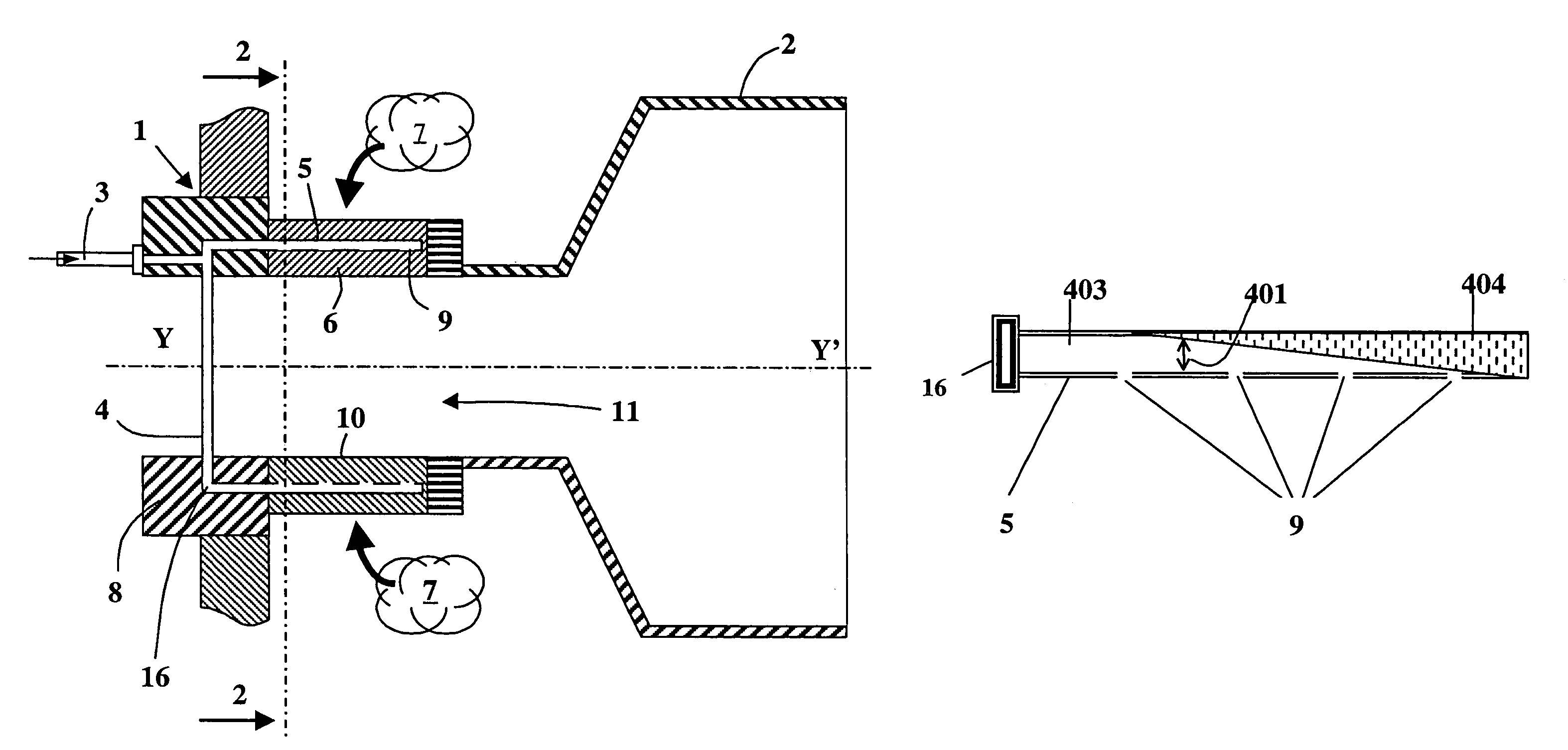
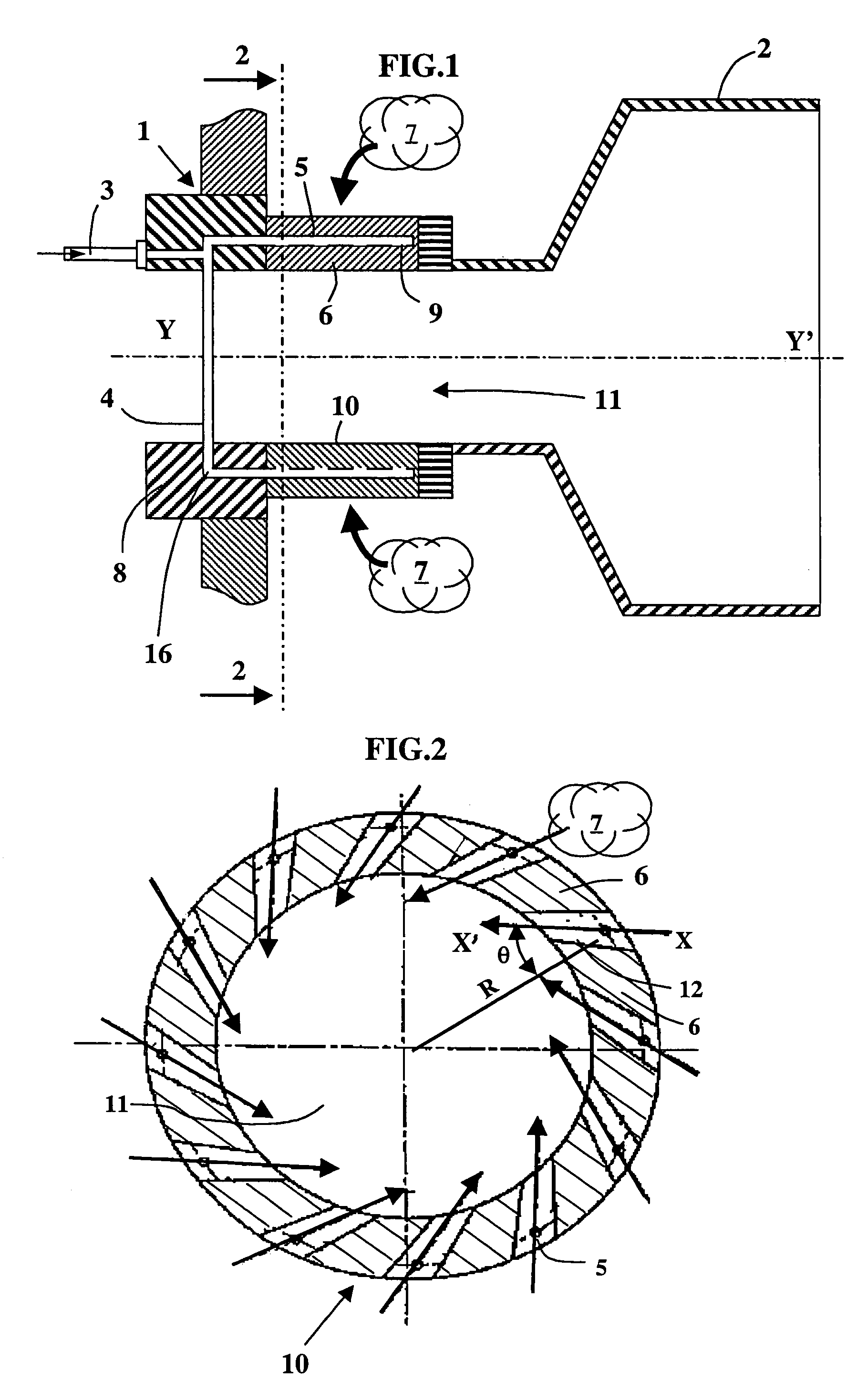
[0046]FIG. 1 is a cross-sectional view of a fuel injection and air supply device 1 opening onto a combustion chamber 2 of a pilot stage or of a main stage of a gas turbine for example.

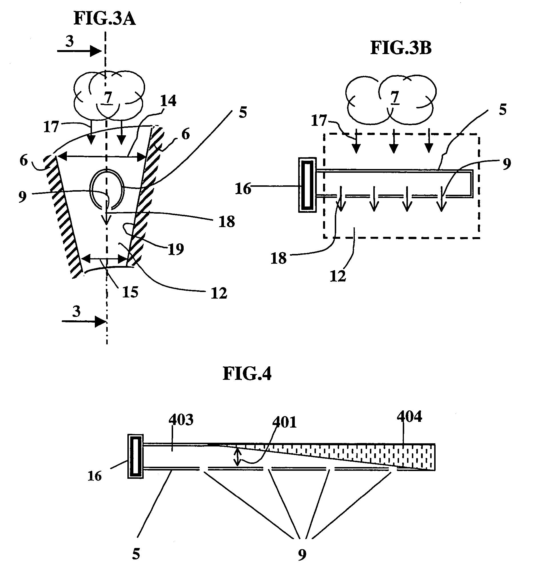
[0047]This device 1, of longitudinal axis YY′, comprises a liquid fuel inlet pipe 3 leading said fuel to a delivery pipe or ramp 4 of substantially annular shape. A multiplicity of channels or pipes 5 communicating with pipe 4 by means of injection points 16 extend substantially axially in the space contained between two blades 6 of a hollow body 10 of substantially cylindrical shape, this space forming a vein 12 allowing passage of the fluid, as can be seen more clearly in FIG. 2.

[0048]Hollow body 10 delimits a central zone 11 whose cross-section is illustrated by FIG. 2. A swirling motion of the air due to its passage between blades 6 allows better stabilization of ...


PUM


Abstract

The present invention relates to a device for injecting a liquid fuel into a pressurized air flow (7), in particular for a combustion chamber, comprising a hollow cylindrical body (10) of longitudinal axis (YY′) delimiting a substantially cylindrical central volume (11), fluid veins (12) substantially radial in relation to the longitudinal axis of body (10) and arranged on the periphery of said body to allow passage of said flow, and axial fuel injection pipes (5) arranged inside said fluid veins and connected to at least one fuel inlet (3) by at least one supply point (16). According to the invention, pipes (5) are pierced with openings (9) that open onto central volume (11) of said body (10) and which are oriented substantially in the direction of the flow in fluid veins (12).

Description

FIELD OF THE INVENTION[0001]The present invention relates to a device and to a method for injecting a liquid fuel into an air flow allowing to obtain a homogeneous fuel / air mixture in a combustion chamber.[0002]The invention finds applications in particular in the sphere of onshore gas turbines by allowing to obtain, during operation of said turbine, a high energy efficiency together with a low pollutant production.BACKGROUND OF THE INVENTION[0003]In conventional combustion chambers for gas turbines, the main priority is to obtain a stable combustion in a wide range of operating conditions.[0004]In order to reach this goal in the most effective way, a combustion is conventionally first carried out under conditions close to stoichiometry with part of the air coming from the compressor, and the fumes obtained are then progressively diluted with another part of the air coming from this compressor so as to lower their temperature to the thermal level allowable by the expander.[0005]This...

Claims


Application Information

Patent Timeline
Patent Type & Authority Patents(United States)
IPC IPC(8): F02C7/22F02C7/26F23R3/14F02C3/30F23C7/00F23D17/00F23R3/00F23R3/12F23R3/28
CPCF23C7/002F23D17/002F23R3/286
Inventor NIASS, TIDJANIMARTIN, GERARDLEBAS, ETIENNEGRIENCHE, GUYSCHOTT, GERARDVERDIER, HUBERT
Owner SAFRAN HELICOPTER ENGINES
Why Eureka
Try Eureka