
Backing sheet, and system and method of fabrication thereof

a technology of backing sheet and backing plate, which is applied in the field of backing sheet, can solve the problems of easy opening and unfolding of the backing plate along the second fold

Inactive Publication Date: 2007-07-31
CERTAINTEED CORP
View PDF10 Cites 5 Cited by
  • Summary
  • Abstract
  • Description
  • Claims
  • Application Information

AI Technical Summary

Benefits of technology

[0007]An object of the present invention is to provide a backing sheet and a system and method of making a backing sheet having a stapling tab that remains fixed to an adjacent portion of the backing sheet during manufacturing and packaging. By insuring that the stapling tabs remains in a fixed position during manufacturing and packaging, the stapling tabs can be prevented from being caught and torn by the conveyor belt and prevented from opening during stacking of the sheets of insulation.
[0008]A further object of the present invention is to provide a backing sheet and a system and method of making a backing sheet having a stapling tab that is not permanently fixed to adjacent portion of the backing sheet such that the installer of the insulation can easily open the stapling tab during installation.
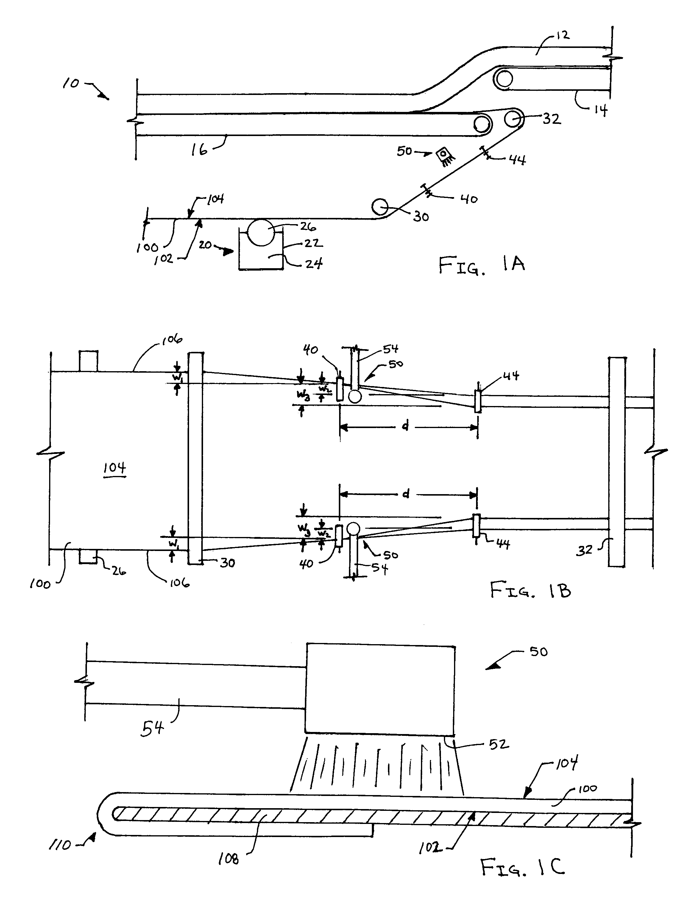
[0011]The tacky substance is preferably a starch solution, although alternative materials can be used. The material used should provide at least a minimal level of adhesion between the stapling tab and the adjacent portion of the backing sheet such that the stapling tab remains fixed to the adjacent portion of the backing sheet during manufacturing and packaging, yet is not permanently fixed to adjacent portion of the backing sheet such that the installer of the insulation can easily unfold the second fold thereby opening the stapling tabs during installation. The concentration of the material can be varied depending upon the length of the assembly line used during the manufacturing and packaging of the insulation, and the length of time the insulation is handled during manufacturing and packaging. If the insulation is going to be frequently handled for a long period of time after the second fold is formed, then a higher concentration of tacky material in the solution will be required in order to insure that the stapling tab remains fixed to the adjacent portion of the backing sheet during the manufacturing and packaging process. The amount of tacky material being sprayed depends upon the desired level of fixation between the stapling tab and the adjacent portion of the backing sheet, and on the line speed of the assembly line (i.e. the speed at which the backing sheet is being fed along the assembly line). The use of a heated roller after the second folders perform the second fold will help insure that the tacky material is dried and set during the remainder of the manufacturing and packaging process. The fiberglass material is then positioned on top of the first side of the backing sheet such that the adherent layer joins the fiberglass material to the backing sheet to form the fiberglass insulation. The fiberglass insulation continues along a conveyor system towards any further manufacturing process areas and packaging areas.
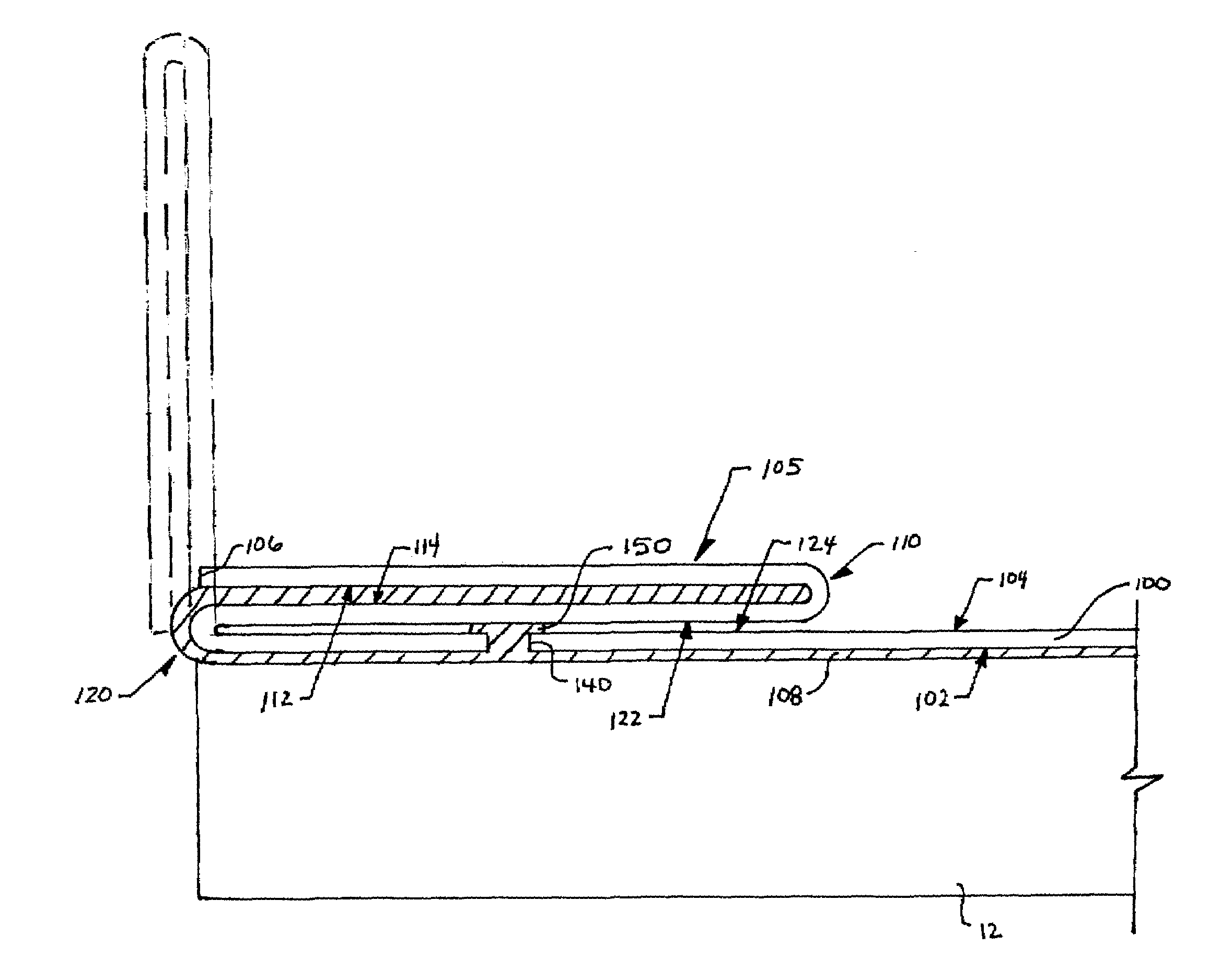
[0012]A third embodiment of a system and method of manufacturing a backing sheet includes a piecing device in place of or in addition to the applicator device of the first and second embodiments. The piercing device is configured to piece a hole through the backing sheet in order to allow a portion of adherent material in the adherent material layer to leak through the hole and contact a portion of the backing sheet. The hole is pierced by punching or cutting a portion of material from the backing sheet to form the hole, or by poking a sharp point through the backing sheet without removing any material or only slightly removing some material from the backing sheet. Preferably the piercing device is located upstream in the system of the roller applying the adherent material, therefore, as the backing sheet travels over the roller, adherent material applied to the first side of the backing sheet will seep or leak through the hole and a portion of the adherent material will extend slightly above the second side. Once the second fold is made, the portion of adherent material extending through the hole will contact a portion of the backing sheet and will adhere to the portion of the backing material it contacts, and thereby prevent the stapling tab from opening during the remaining manufacturing and packaging processes.

Problems solved by technology

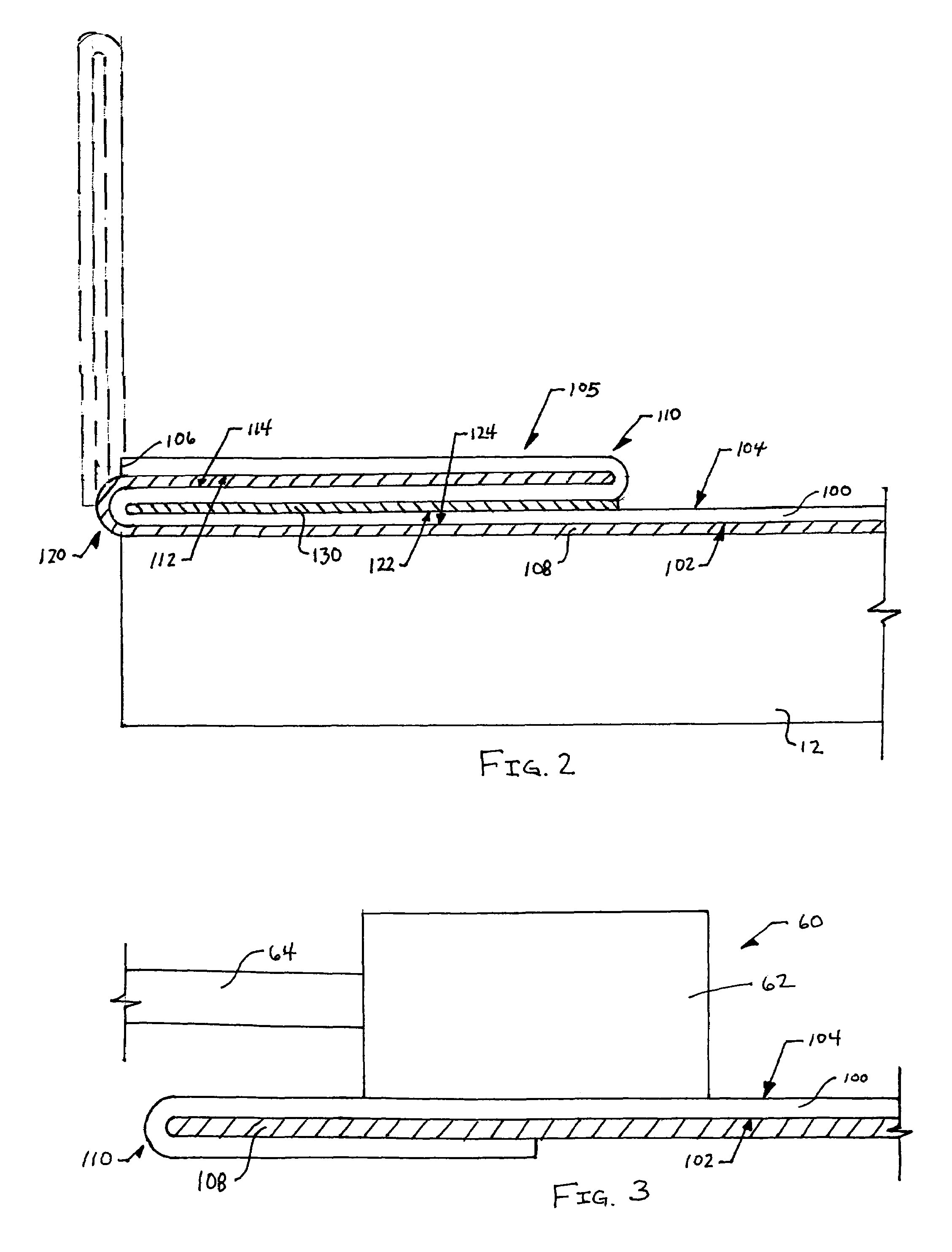
Notice that without any type of means for joining the first portion of the second side to the second portion of the second side, the stapling tab would be prone to open and unfold along the second fold during the manufacturing processes occurring downstream, such as the feeding of the insulation on conveyor belts and the movement of the insulation during packaging processes.

Method used


Image

  • Backing sheet, and system and method of fabrication thereof
  • Backing sheet, and system and method of fabrication thereof
  • Backing sheet, and system and method of fabrication thereof

Examples


first embodiment

[0024]FIGS. 1A through 1C depict a system and method of manufacturing a backing sheet according to the present invention. Specifically, FIG. 1A depicts a side schematic view of section of a system 10 used to manufacture a backing sheet 100. This embodiment of the present invention is particularly well suited for manufacturing a backing sheet that can be attached to a sheet of fiberglass material 12 to form fiberglass insulation that is configured for installation between the structural beams within a wall. The method and system of the present invention forms one portion of the manufacturing process used to construct the fiberglass insulation. FIG. 2 depicts is an embodiment of a backing sheet 100 according to the present invention, which can be produced, for example, by the system and method depicted in FIGS. 1A through 1C.

[0025]The system 10 of the first embodiment includes a roller device 20 configured to apply an adherent material 24 to a first side 102 of the backing sheet 100. ...

third embodiment

[0040]the system and method of manufacturing a backing sheet includes a piecing device 70 configured to piece a hole 140 through the backing sheet 100 in order to allow a portion of adherent material in the adherent material layer 108 to leak through the hole 140 and contact a portion of the backing sheet 100. The hole 140 is pierced by punching or cutting a portion of material from the backing sheet 100 to form the hole 140, or by poking a sharp point through the backing sheet 100 without removing any material or only slightly removing some material from the backing sheet 100. The piercing of the hole 140 can be accomplished using a variety of alternative types of piecing devices, one embodiment of which will be described below.

[0041]Preferably the piercing device 70 is located upstream in the system of the roller 26, therefore, as the backing sheet 100 travels over the roller 26, adherent material 24 applied to the first side 102 of the backing sheet 100 will seep or leak through ...


PUM

PropertyMeasurementUnit
tackyaaaaaaaaaa
adhesionaaaaaaaaaa
concentrationaaaaaaaaaa

Abstract

A backing sheet, and a system and method of manufacturing a backing sheet with stapling tabs. The system includes a roller device configured to apply an adherent material to a first side of the backing sheet continuously fed from a feed roll. The sheet is then fed to a first pair of folders configured to fold the backing sheet along the edges such that the adherent material holds the first fold in place. The sheet passes through a second pair of folders that form a second fold along the edges of the sheet by folding in the opposite direction as in the first fold. Advantageously, an applicator device is configured to apply a tacky substance, such as a starch solution, between the contacting portions of the second fold, prior to the formation of the second fold. The tacky substance maintains the second fold and prevents the stapling tab from opening during further manufacturing and packaging processes. Alternatively, the system includes a piercing device configured to piece a hole through the backing sheet in order to allow a portion of adherent material to leak through the hole and contact a portion of the backing sheet. Once the second fold is made, the portion of adherent material extending through the hole will contact a portion of the backing sheet and will adhere to the portion of the backing material it contacts, and thereby prevent the stapling tab from opening during the remaining manufacturing and packaging processes.

Description

BACKGROUND OF THE INVENTION[0001]1. Field of the Invention[0002]The present invention relates generally to a backing sheet, as well as, a system and method of fabricating a backing sheet. More specifically, the present invention relates backing sheets having stapling tabs.[0003]2. Discussion of the Background[0004]Conveyor belt systems are typically used during the manufacture of various products to move the product from one processing station to another. One problem that arises with the use of conveyor belt systems is that if the product becomes caught on the edge of a conveyor belt then the product may become damaged. For example, fiberglass insulation can be manufactured with a backing sheet having a stapling tab on both edges of the sheet. The stapling tabs are configured to be utilized during the installation of the fiberglass insulation by placing the insulation between structural support members, folding the tabs outward into an open position, and stapling the tabs to the str...

Claims


Application Information

Patent Timeline
Patent Type & Authority Patents(United States)
IPC IPC(8): B32B3/04B32B7/04B65H45/22B65H45/30E04B1/78
CPCB32B3/04B32B7/04B65H45/22B65H45/30E04B1/78B65H2701/1315Y10T428/24231Y10T156/103Y10T428/24339Y10T428/24215Y10T428/24264Y10T428/2419Y10T428/24331Y10T428/28
Inventor SUDA, DAVIDCUTHBERTSON, TOMBUSCHER, MARKCLEVENSTINE, LARRY
Owner CERTAINTEED CORP
Learn More