VDT stress mitigating device and method, VDT stress risk quantifying device and method, and recording medium

a technology of video display device and stress risk, which is applied in the field of video display device stress mitigating device and method, and vdt stress risk quantifying device and method, can solve the problems of inability to mitigate content in principle, no known technology for mitigating content generated vdt stress, and excessive strain and fatigue, so as to prevent any harmful health effects, reduce the risk of vdt stress, and reduce the excessive stress on the person viewing the video display device

Inactive Publication Date: 2007-07-31
NEC CORP
View PDF17 Cites 6 Cited by
  • Summary
  • Abstract
  • Description
  • Claims
  • Application Information

AI Technical Summary

Benefits of technology

[0043]According to the present invention, the power of spatial frequency components that are contained in moving images or static images on a display device and are the highest spatial frequency components in a direction orthogonal to the scan line direction capable of being displayed on that display device is detected. In addition, the power of temporal frequency components equivalent to the frame scan frequency of interlaced scan format video signals displayed on the display device is detected. Then on the basis of this, the power of the highest spatial frequency components in a direction orthogonal to the scan line direction capable of being displayed on the display device and that are contained in the displayed images, and the power of temporal frequency components equivalent to the frame scan frequency of interlaced scan format video signals displayed on the display device are attenuated. As a result, content generated VDT stress caused by flicker generated by fine striped patterns in a direction orthogonal to the scan line direction and fine striped patterns, having an equal pitch and parallel to the scan line, are mitigated. In addition, the risk of VDT stress caused by the power of the highest spatial frequency components in a direction orthogonal to the scan line direction capable of being displayed on the display device, and the power of temporal frequency components equivalent to the frame scan frequency is quantified.
[0044]In this way, according to the present invention, the size of the power of flicker components of a temporal frequency equivalent to the frame scan frequency generated by images having a pattern of equally pitched stripes parallel to a horizontal scan line of a display device for displaying interlaced format graphic signals is detected. By then appropriately attenuating the power of these components according to the above size, excessive stress on a person viewing the video display device is reduced, and it is possible to prevent any harmful health effects arising therefrom.

Problems solved by technology

There have been reports that, due to this type of content generated VDT stress, excessive strain and fatigue is caused in the cranial nervous system and the like, and that symptoms resembling travel sickness and, in some cases, even convulsions have been caused.
However, at present, there is no known technology for mitigating content generated VDT stress caused by this type of regular spatial pattern or for detecting the degree of risk of this type of VDT trouble.
However, because this technology performs a temporal filtering process on each pixel independently, it is not possible in principle to mitigate content generated VDT stress caused by regular spatial patterns contained in the graphics, or VDT stress caused by the aforementioned flicker generated when field images are displayed alternately in an interlaced format.
Moreover, nor is it possible to quantatively detect the risk of this type of VDT stress.

Method used


Image

  • VDT stress mitigating device and method, VDT stress risk quantifying device and method, and recording medium
  • VDT stress mitigating device and method, VDT stress risk quantifying device and method, and recording medium
  • VDT stress mitigating device and method, VDT stress risk quantifying device and method, and recording medium

Examples


first embodiment

§ 1. First Embodiment

[0063]First, the first embodiment of the present invention will be described.

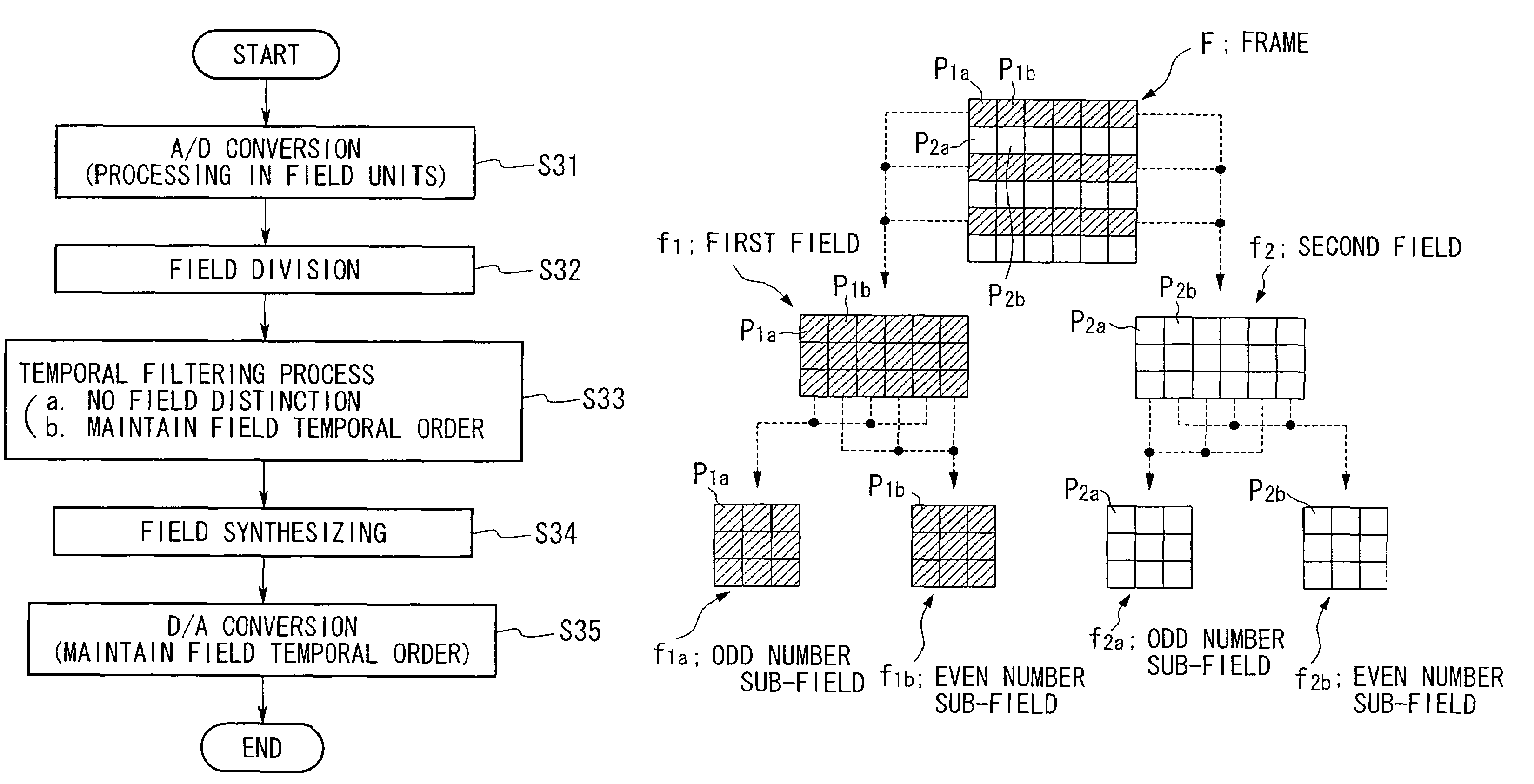
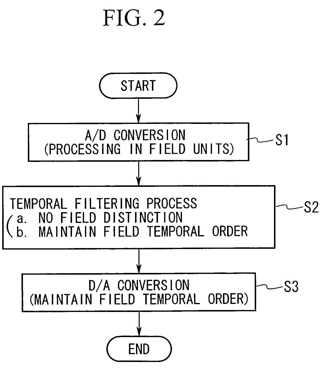
[0064]The VDT stress mitigating device according to the first embodiment is installed between an image signal output device such as a video tuner and an image display device such as a video monitor, and, without distinguishing between the first field and second field, performs a temporal filtering process for each field on a video signal (image signal) based on an interlaced format such as NTSC or PAL.

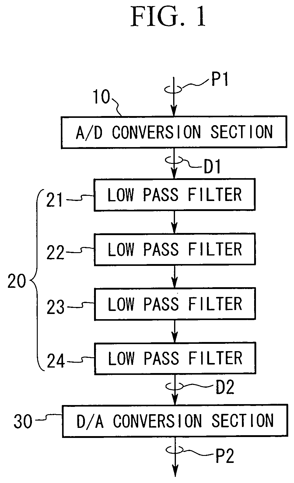
[0065]FIG. 1 shows the structure of the VDT stress mitigating device according to the first embodiment. In FIG. 1, the symbol 10 denotes an A / D conversion section. The A / D conversion section 10 sequentially imports analog quantity video signals P1 based on an interlaced format from an unillustrated external image signal output device in field units, and converts these to digital quantity image data (numerical data) D1 by A / D conversion. The symbol 20 denotes a filter section comprising low...

second embodiment

§ 2. Second Embodiment

[0099]The second embodiment of the present invention will be described next.

[0100]The second embodiment deals with a VDT stress risk quantifying device for quantifying and detecting the risk of VDT stress caused by images based on an interlaced format such as NTSC or PAL.

[0101]FIG. 6 shows the structure of the VDT stress risk quantifying device according to the second embodiment. In FIG. 6, the symbol 10 refers to an A / D conversion section. The A / D conversion section 10 sequentially imports from the outside in field units analog quantity video signals P1 based on an interlaced format and converts these into image data D1 by A / D conversion.

[0102]The symbol 100 refers to a risk quantifying section forming the feature portion of the VDT stress risk quantifying device according to the second embodiment. The risk quantifying section 100 comprises: field memory 101 for importing the image data D1 of a single field and temporarily holding it; a low pass filter 102 for...

third embodiment

§ 3. Third Embodiment

[0122]The third embodiment of the present invention will be described next.

[0123]In the third embodiment of the present invention, the functions of the risk quantifying device of the second embodiment are given to the VDT stress mitigating device according to the first embodiment, thereby allowing the risk index value e(t) to be reflected in the blurring constant δ, and enabling the filter characteristics to be appropriately controlled in accordance with the degree of risk of VDT stress.

[0124]The structure of the VDT stress mitigating device according to the third embodiment is shown in FIG. 8. In FIG. 8, the symbol 10 denotes an A / D conversion section the same as that described in the first embodiment. The A / D conversion section 10 converts interlaced format image signals P1 into image data D1 by A / D conversion and then outputs the image data D1. The symbol 100 denotes a risk quantifying section having the same structure as that described in the second embodime...


PUM


Abstract

The aim of the present invention is to provide a VDT stress mitigating device and method capable of mitigating VDT stress caused by a regular spatial pattern and VDT stress caused by flicker generated by an interlaced format, a VDT stress risk quantifying device and method, and a recording medium. An A / D conversion section 10 imports interlaced format video signals P1 from an external image signal output device and converts them in field units by A / D conversion into image data D1. A filter section 20, while not distinguishing between the first field and the second field, and while maintaining the temporal order of these fields, performs a temporal filtering process on the image data of each field. A D / A conversion section 30 converts the image data D2 that has undergone the temporal filtering process by the filter section 20 into image signals P2 based on an interlaced format by D / A conversion. The image signals P2 are then sequentially outputs according to the temporal order of the fields.

Description

CROSS-REFERENCE TO RELATED APPLICATIONS[0001]This application is a divisional of U.S. Application No. 09 / 717,499, filed on Nov. 21, 2000, now abandoned which claims the benefit of Japanese Application No. 11-333429 filed in Japan on Nov. 24, 1999, the contents of both which are incorporated herein in their entirety by this reference.BACKGROUND OF THE INVENTION[0002]1. Field of the Invention[0003]The present invention relates to a VDT (video display terminal) stress mitigating device and method, a VDT stress risk quantifying device and method, and a recording medium for reducing VDT stress such as excessive strain and fatigue caused by visual irritation.[0004]The present application is based on an application for a patent in Japan (Japanese Patent Application Laid-Open (JP-A) No. 11-333429) and the contents disclosed in the above Japanese patent application have been incorporated as a portion of the present specification by reference.[0005]2. Description of the Related Art[0006]Conve...

Claims


Application Information

Patent Timeline
Patent Type & Authority Patents(United States)
IPC IPC(8): H04N5/00G06K9/40H04N5/21H04N9/77H04N9/78H04N5/66G09G5/00G09G5/24G09G5/36G09G5/42H04N5/65
CPCG09G5/00G09G5/24G09G5/42H04N7/0132G09G2310/0224G09G2320/0247H04N5/65
Inventor NOMURA, LEGAL REPRESENTATIVE, NAOKONOMURA, DECEASED, MASAHIDE
Owner NEC CORP
Why Eureka
Try Eureka