Method for monitoring end of life for battery

Inactive Publication Date: 2007-07-31
CARDIAC PACEMAKERS INC
View PDF65 Cites 185 Cited by
  • Summary
  • Abstract
  • Description
  • Claims
  • Application Information

AI Technical Summary

Benefits of technology

[0034]The process may use a period immediately following an atrial pace or atrial pulse (e.g., where

Problems solved by technology

The lifetime of such cells is not great enough to outlast the patient, so the industry has experienced occurrences where such batteries have come to their End Of Life (EOL) under nominal loads and normal circumstances.
In the pacemaker environment, since there is constant (but not uniform) energy depletion, this component of the internal impedance increases continually with time.
However, and particularly for a demand pacer which at any time may or may not be delivering stimulus pulses, the increase of this component is not linear with time, due to the fact that current drain is not uniformly constant.
Since the internal impedance of the source rises drastically after the knee, the battery may have very little or no useful lifetime left after the knee has been reached and passed.
However, this is a highly tenuous and very unsatisfactory premise for determining EOL, due to the fact that actual current drain near EOL cannot be predicted nor directly measured with ease.
Accordingly, if the EOL design is predicated upon sensing voltage drop to a

Method used


Image

  • Method for monitoring end of life for battery
  • Method for monitoring end of life for battery
  • Method for monitoring end of life for battery

Examples


Embodiment Construction

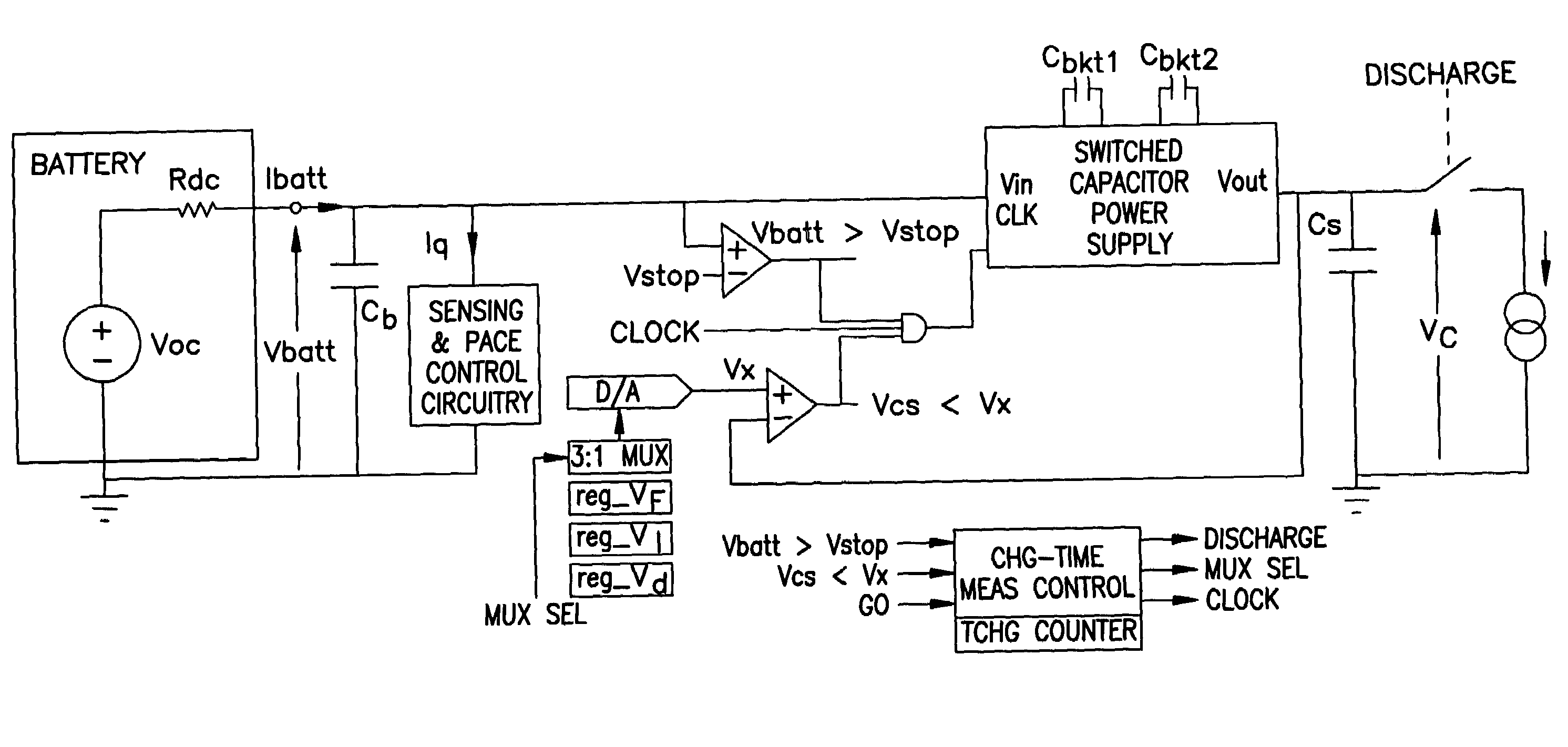
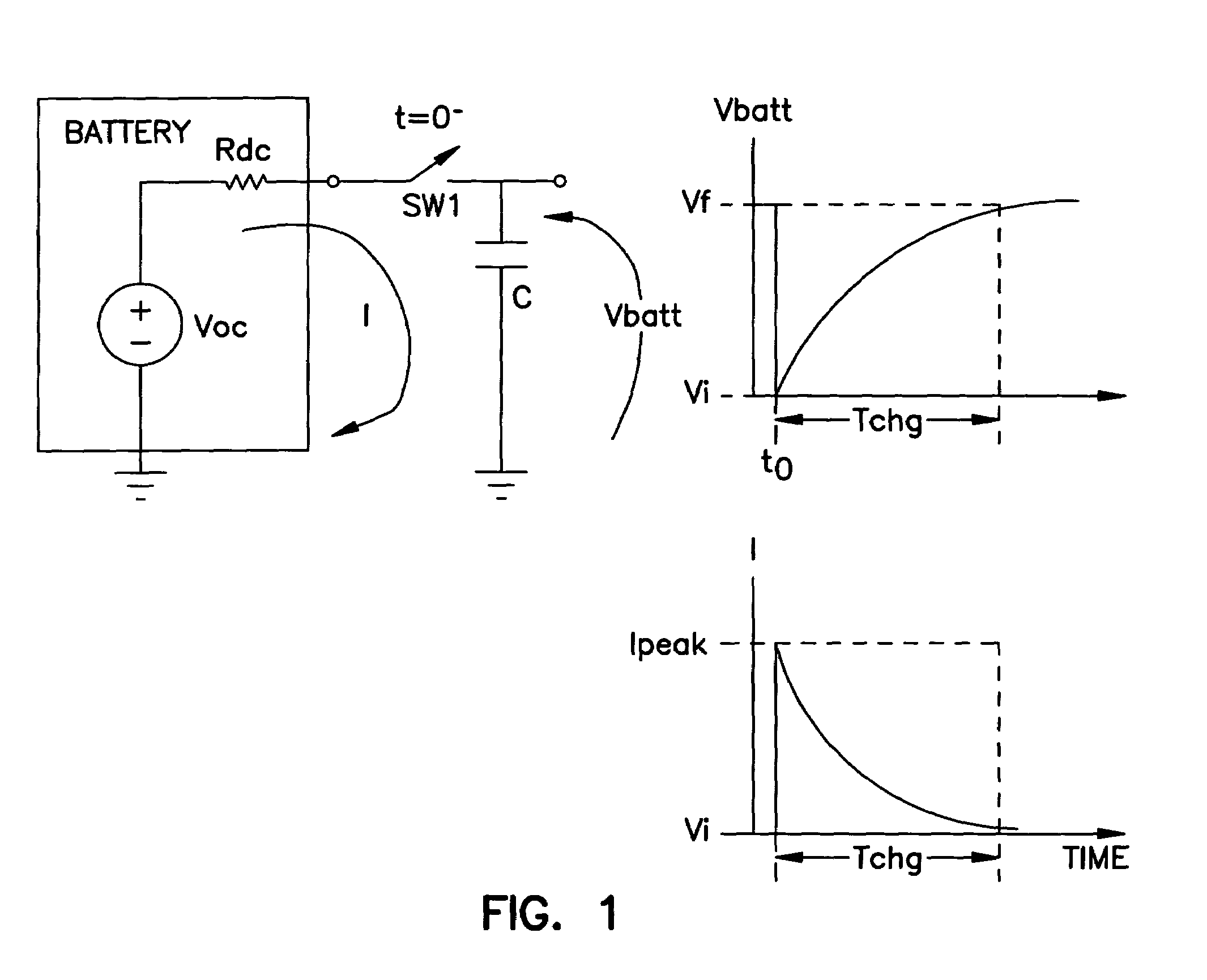
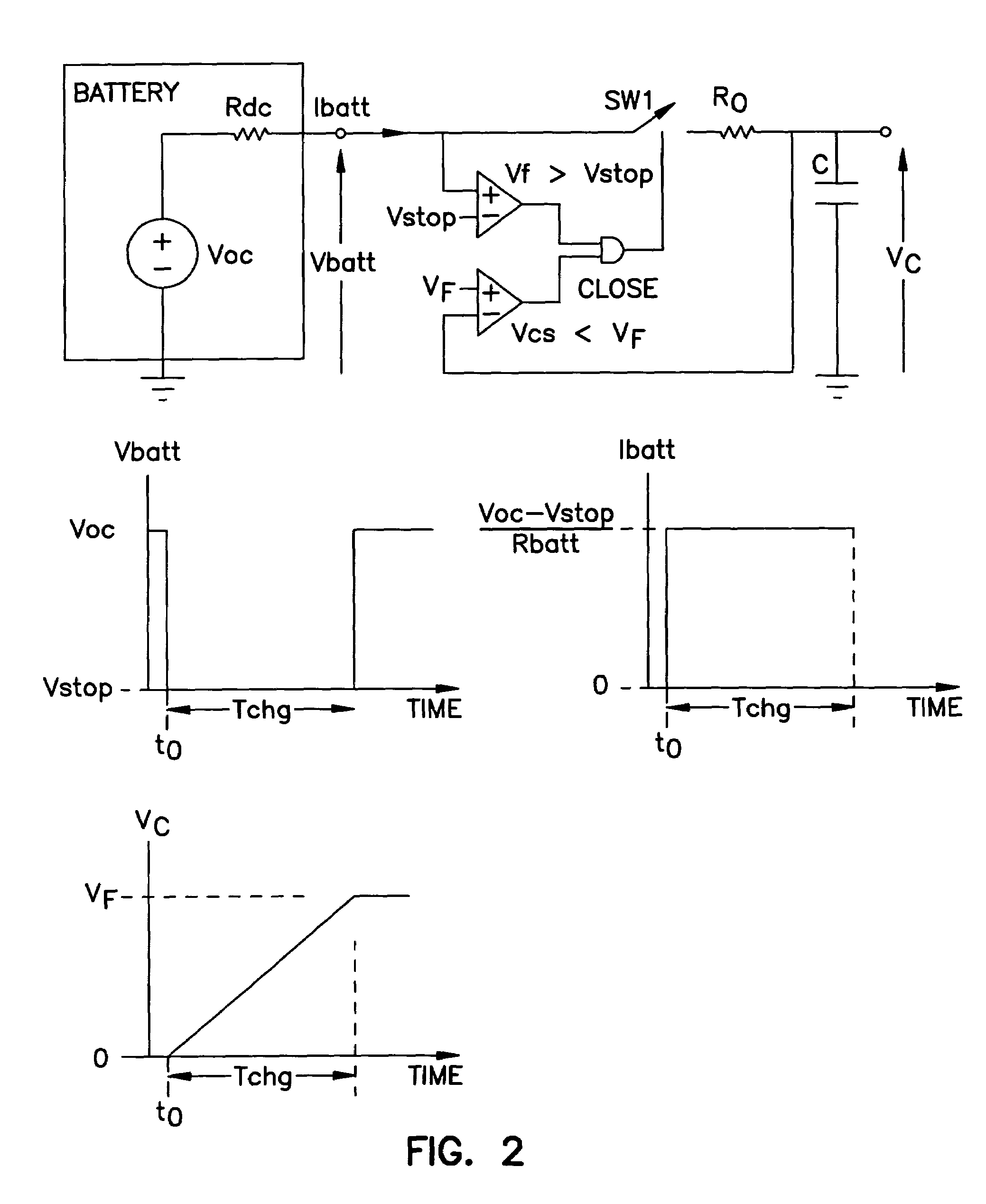
[0035]The term “lithium-type” as used herein refers to the lithium iodine battery as well as other lithium systems such as those disclosed in the aforementioned article of Parsonnet et al. More broadly, the term “lithium-type” refers to a battery or cell having approximately the characteristics displayed by the lithium iodine battery. The cell has an effective open circuit voltage E0 which, by way of illustration, is about 2.8 volts for the Catalyst Research battery. The effective internal impedance in series with E0 comprises 2 impedance components. The first impedance component, shown as RL, represents the resistance to the travel of Li+ ions through the LiI layer. This resistance is a direct linear function of the charge or energy drawn from the battery, such that this component is linear as a function of battery usage. As is well understood in the art, as the charge production from the battery increases (higher Milliampere Hours), the Internal Impedance increases. The increased ...


PUM


Abstract

A system is described. The system includes a lithium battery, a charge storage capacitor electrically connected to the lithium battery, a first device, and at least one second device. The first device is electrically connected to the lithium battery and is powered by the lithium battery. The at least one second device is attached to the charge storage capacitor and adapted to read a rate of charge storage in the charge storage capacitor or to calculate the rate of charge storage by measuring both a time of charging and a charge stored or added to the charge storage capacitor during the time of charging.

Description

CROSS-REFERENCE TO RELATED APPLICATION(S)[0001]This application is a division of U.S. patent application Ser. No. 10 / 093,141, filed on Mar. 6, 2002, now U.S. Pat. No. 6,654,640 which is a continuation of U.S. patent application Ser. No. 09 / 670,653, filed on Sep. 27, 2000, now abandoned, which is a division of U.S. patent application Ser. No. 08 / 929,629, filed on Sep. 15, 1997, now issued as U.S. Pat. No. 6,167,309, the specifications of which are incorporated herein by reference.FIELD OF THE INVENTION[0002]The present invention relates to a method of determining when the end of life of a battery is approaching, and circuitry which may be used with that process. The invention particularly relates to such methods where access to the battery for conventional testing means is not readily available, where maintenance of sufficient levels of power from the battery are important with minimal interruption, and for monitoring of battery power in pacemakers.BACKGROUND OF THE ART[0003]Over the...

Claims


Application Information

Patent Timeline
IPC IPC(8): A61N1/37G01R31/36
CPCA61N1/3708A61N1/378G01R31/3651G01R31/3693H02J2007/005G01R31/3647G01R31/367H02J7/0048H02J7/005H02J2310/23
Inventor LYDEN, MICHAEL J.
Owner CARDIAC PACEMAKERS INC
Why Eureka
Try Eureka