Environmental control unit for hospital room

a technology for controlling units and hospital rooms, applied in the field of room air conditioning and filtration equipment, can solve the problems of difficult conversion of positive pressure rooms, limiting the flexibility of a hospital to deal with emergency situations, and high construction costs of isolation rooms, and achieve the effect of convenient installation

Active Publication Date: 2007-08-07
AIR INNOVATIONS
View PDF9 Cites 42 Cited by
  • Summary
  • Abstract
  • Description
  • Claims
  • Application Information

AI Technical Summary

Benefits of technology

[0009]It is an object to provide a unit for cleaning and conditioning of air in a room that can be easily installed in an existing room to create an isolation space having net positive pressure or net negative pressure, as needed, and which avoids the drawbacks of the prior art.
[0011]It is a more particular object to create a self-contained unit that can be easily and reliably installed by hospital personnel with only a minimum of special training and without need for special tools.
[0013]According to one aspect of the present invention, an air passage or air plenum is added to provide a controllable passageway which allows fresh air to be drawn into the evaporator system to positively pressurize the room, or to draw off some of the conditioned air from downstream of the evaporator fan to negatively pressurize the room. Since the make-up air enters upstream of the UV tubes and upstream of the HEPA filter, it is treated before it enters the room so as to protect the patient. The amount of this fresh air is controlled by adjusting a slide damper inside the cabinet. If the slide damper is moved to another position, the damper closes the fresh air passageway to the evaporator return plenum, and opens a passageway from the supply plenum to the condenser air plenum. In this position the room can be negatively pressurized. A portion of the supply air, which has been treated by the UV tubes and the HEPA filter, is drawn into the condenser air flow, and the condenser fan exhausts it outside the room, either to the outside air or into the building HVAC system with the rest of the condenser air. The air evacuated from the room is UV treated and filtered, which protects persons outside from contamination or contagion.
[0017]In one embodiment, a slide baffle controls the communication of air between the return plenum or the supply plenum and the pressurization control plenum, which in turn communicates with the condenser air pathway. The slide baffle can be moved to positions for positive pressure, negative pressure, or neutral. This can be done by hand, or by means of a linear motor. Openings on the slide baffle line up with vent openings on the side of the return plenum and the supply plenum, depending on whether positive or negative pressure is needed. These can be partially or fully aligned, so that the amount of pressurization can be controlled.
[0018]In another embodiment, the slide baffle can control the air flow into the common intake plenum from a first (room-air) inlet and a second (outside-air) inlet, which may be connected via a duct to the supply ducting of the building air conditioning. By moving the slide, one inlet or the other is opened, and the other closed, and this controls whether the room has a net positive pressure or net negative pressure. It is possible to move the slide baffle to a mid-way or neutral position so that both are partly open, which can be used to create a neutral room pressure.

Problems solved by technology

One reason for this is because isolation rooms are very expensive to build because they conventionally require separate, independent HVAC systems for each room to prevent the spread of contaminants to other areas of the hospital.
However, even with isolation HVAC systems the rooms are not easy to convert from positive pressure to negative pressure or vice versa.
These rooms are generally built either for positive pressure only or for negative pressure only, and this limits the flexibility of a hospital to deal with emergency situations.

Method used


Image

  • Environmental control unit for hospital room
  • Environmental control unit for hospital room
  • Environmental control unit for hospital room

Examples


Embodiment Construction

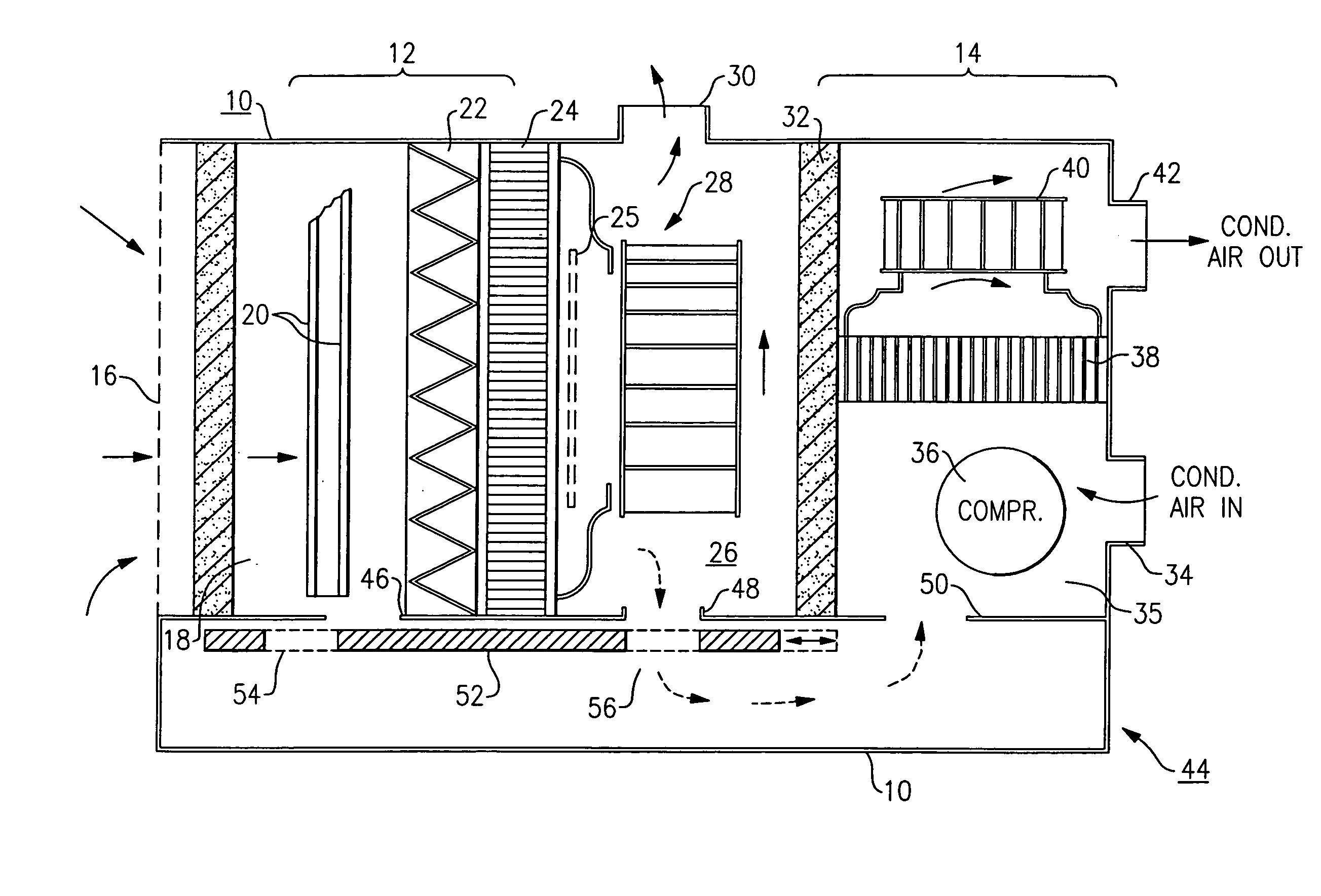
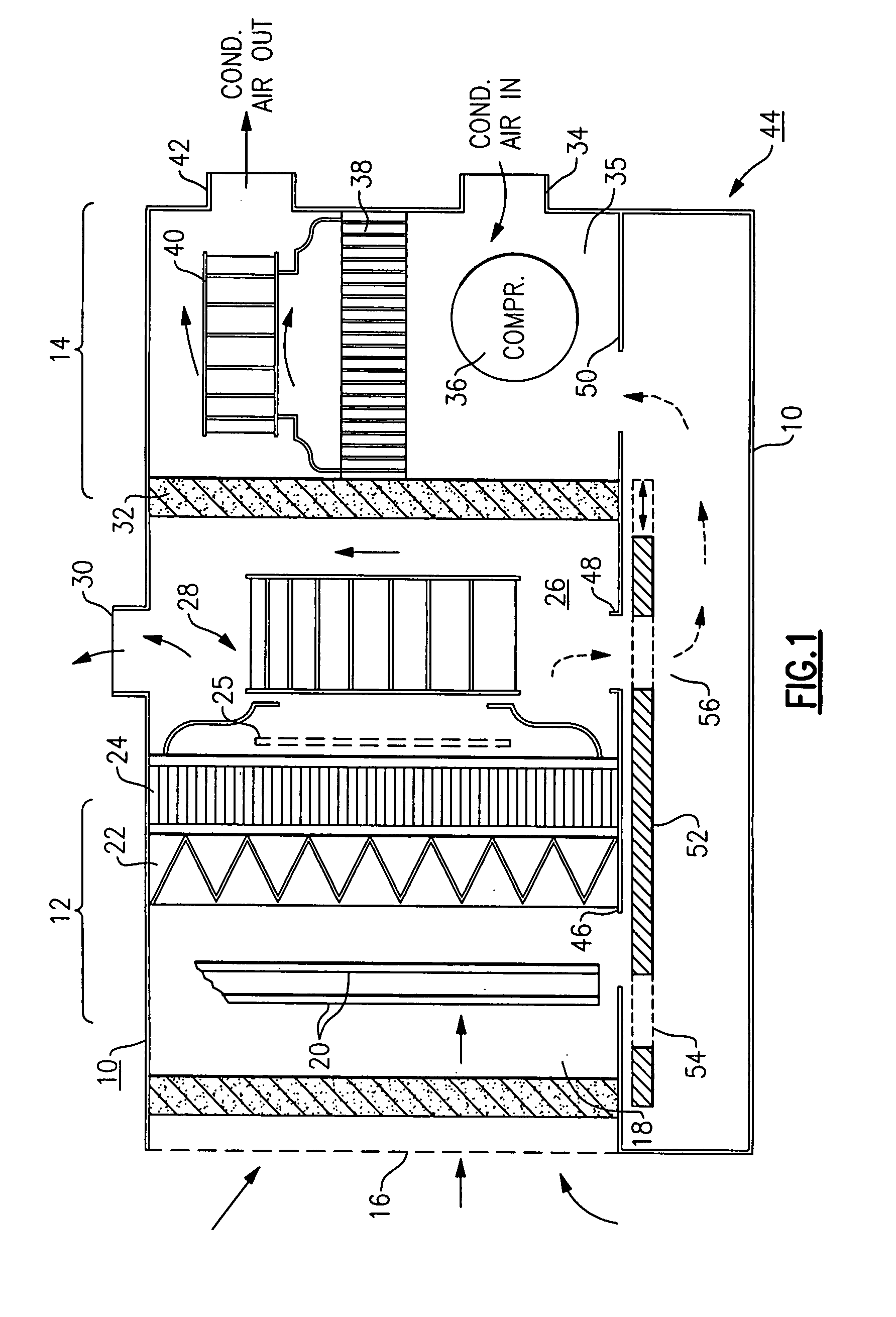
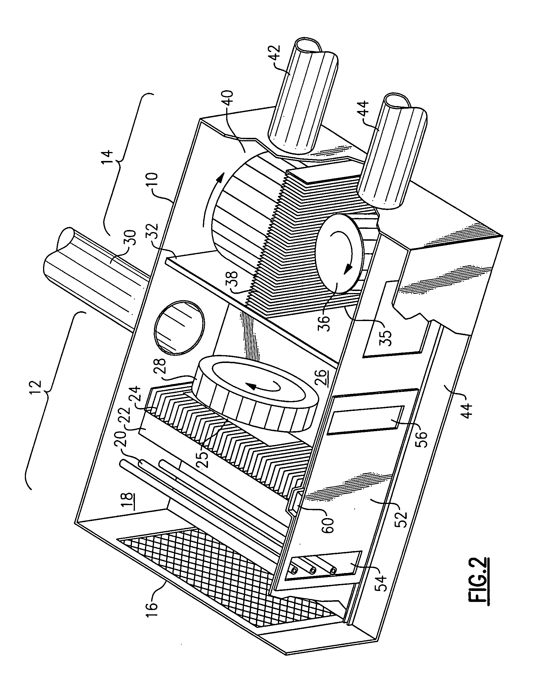
[0027]With reference to the drawing Figures, FIGS. 1 and 2 show the general construction of the hospital environmental control unit of one possible embodiment, with a housing or enclosure 10, and an indoor or evaporator side 12 and an outside air or condenser side 14. The indoor evaporator side 12 has an intake grille 16, which serves as inlet for return air from the conditioned room environment, and the grille may incorporate a pre-filter. This leads to a return plenum 18 in which there are UV tubes 20 that provide sterilizing ultraviolet radiation for killing airborne pathogens. After this the return air passes through a HEPA filter 22 and then through an evaporator coil 24 that chills and dehumidifies the air. An electric heat coil 25 may be present for reheating the air, as necessary to control room temperature. The UV tubes 20 also illuminate the HEPA filter 22 to kill any bacteria or other pathogens that become trapped on the filter. After this, a supply plenum 26 includes a f...


PUM


Abstract

An air conditioner and filtering unit produces a positive or negative pressure to create an isolation space. A common air intake plenum has first and second inlets for admitting return air from the space or outside air which may be from a building main A / C system supply. Sanitized, cleaned and conditioned air is returned to the conditioned space; and condenser air is exhausted outside the conditioned space. The air intake plenum may be common to both the condenser air flow and to the evaporator air flow. A HEPA filter cleans the air suppled to both the condenser and the evaporator. A slide damper or other arrangement selectively opens and closes air flow through the first and second air inlets into the common intake plenum. This permits creation of overpressure, underpressure, or an intermediate pressure in the conditioned space. All air supplied to the room and all air exhausted from the room is cleaned and sanitized. The unit is self-contained and portable.

Description

[0001]Priority is claimed of U.S. Provisional Application No. 60 / 591,135, filed Jul. 27, 2004, the disclosure of which is incorporated by reference.BACKGROUND OF THE INVENTION[0002]The invention concerns room air conditioning and filtration equipment, and in particular is directed to a unit that can operated in a positive pressure mode, a negative pressure mode, or a normal mode. The invention is also concerned with units that clean and condition the room air as well as remove or kill airborne pathogens, and which have a mechanism for introducing make-up air to create a positive pressure or overpressure in the room relative to the outside ambient air, or exhausting some of room air to create a negative pressure relative to the outside air. At least one of the inventors is the patentee of U.S. Pat. No. 5,884,500, Mar. 23, 1999 and U.S. Pat. No. 5,987,908, Nov. 23, 1999, which are incorporated herein by reference.[0003]High Efficiency Particulate Air (HEPA) filters are used extensivel...

Claims


Application Information

Patent Timeline
Patent Type & Authority Patents(United States)
IPC IPC(8): F25D17/06
CPCF24F1/025F24F3/161F24F2003/1667F24F2011/0004F24F2011/0005F24F1/022F24F1/04F24F3/167F24F8/22
Inventor WETZEL, MICHAEL L.WETZEL, LAWRENCE E.
Owner AIR INNOVATIONS
Why Eureka
Try Eureka